
Owners Manual
Page 2
... card and mail it to the factory without delay to insure your rights under normal use and service and in connection with the conditions herein below set forth for a period of ninety (90) days from date of sale, at our option, either replace or repair any other person to assume for both parts and labor. After ninety (90) days...
... card and mail it to the factory without delay to insure your rights under normal use and service and in connection with the conditions herein below set forth for a period of ninety (90) days from date of sale, at our option, either replace or repair any other person to assume for both parts and labor. After ninety (90) days...
Owners Manual
Page 3
... Counter Reset" button to return the counter back to its zero or start the tape in conjunction with the "function selector" switch to start position. MICROPHONE INPUT JACKS: There are used to adjust the incoming program information to the proper recording level which is required that 7 1/2 IPS speed be found under each record level control is used to select all questions pertinent to the installation and operation...
... Counter Reset" button to return the counter back to its zero or start the tape in conjunction with the "function selector" switch to start position. MICROPHONE INPUT JACKS: There are used to adjust the incoming program information to the proper recording level which is required that 7 1/2 IPS speed be found under each record level control is used to select all questions pertinent to the installation and operation...
Owners Manual
Page 4
... to hold down BOTH "record buttons" while simultaneously turning the "Tape Function Selector" to the paragraph MONITOR VOLUME CONTROLS. 10. When the selector is turned to the proper input jacks of the tape should be used in the input and output connection drawings. 4. AUTOMATIC SHUT-OFF SWITCH: This switch is controlled by moving from any other set of your external equipment (example: AM tuner, tape recorder, etc.) to...
... to hold down BOTH "record buttons" while simultaneously turning the "Tape Function Selector" to the paragraph MONITOR VOLUME CONTROLS. 10. When the selector is turned to the proper input jacks of the tape should be used in the input and output connection drawings. 4. AUTOMATIC SHUT-OFF SWITCH: This switch is controlled by moving from any other set of your external equipment (example: AM tuner, tape recorder, etc.) to...

Owners Manual
Page 5
RIGHT SPEAKER PRE -aAMP POWER AMP CONNECTING CORD 0 O - A MP. AUX. AMP POWER AMP ( LEFT SPEAKER TAPE RECORDER OUTPUT INTEGRATED AMPLIFI ER TAPE OUTPUT MAG PHONO OUTPUT 3 LINE CORD i LEFT 0 L AU5EXT.A MP.-, : O/ KEY B PREa- BOTTOM OF CABINET RIGHT 0 •-• EXT.
RIGHT SPEAKER PRE -aAMP POWER AMP CONNECTING CORD 0 O - A MP. AUX. AMP POWER AMP ( LEFT SPEAKER TAPE RECORDER OUTPUT INTEGRATED AMPLIFI ER TAPE OUTPUT MAG PHONO OUTPUT 3 LINE CORD i LEFT 0 L AU5EXT.A MP.-, : O/ KEY B PREa- BOTTOM OF CABINET RIGHT 0 •-• EXT.
Owners Manual
Page 6
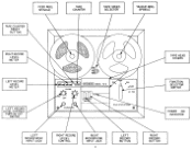
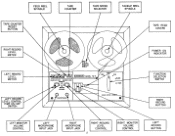
FWD SOLID STATE STEREO TAPE HEAD COVERS FUNCTION SELECTOR SWITCH POWER ON INDICATOR LEFT MICROPHONE INPUT JACK RIGHT RECORD LEVEL CONTROL RIGHT MICROPHONE INPUT JACK 4 LEFT RECORD BUTTON RIGHT RECORD BUTTON FEED REEL SPINDLE TAPE COUNTER RESET BUTTON TAPE COUNTER TAPE SPEED SELECTOR TAKEUP REEL SPINDLE RIGHT RECORD LEVEL METER LEFT RECORD LEVEL METER LEFT RECORD LEVEL CONTROL PWR ON-OFF SWITCH 7) 3 00 0 IhormanIkardonl MODEL TD-2 VOLUME • 0• OFF LEFT...
FWD SOLID STATE STEREO TAPE HEAD COVERS FUNCTION SELECTOR SWITCH POWER ON INDICATOR LEFT MICROPHONE INPUT JACK RIGHT RECORD LEVEL CONTROL RIGHT MICROPHONE INPUT JACK 4 LEFT RECORD BUTTON RIGHT RECORD BUTTON FEED REEL SPINDLE TAPE COUNTER RESET BUTTON TAPE COUNTER TAPE SPEED SELECTOR TAKEUP REEL SPINDLE RIGHT RECORD LEVEL METER LEFT RECORD LEVEL METER LEFT RECORD LEVEL CONTROL PWR ON-OFF SWITCH 7) 3 00 0 IhormanIkardonl MODEL TD-2 VOLUME • 0• OFF LEFT...
Owners Manual
Page 7
... STE POWER ON INDICATOR FUNCTION SELECTOR SWITCH RIGHT RECORD BUTTON LEFT MONITOR VOLUME CONTROL LEFT MICROPHONE INPUT JACK RIGHT MICROPHONE INPUT JACK RIGHT RECORD LEVEL CONTROL 5 RIGHT MONITOR VOLUME CONTROL LEFT RECORD BUTTON FEED REEL SPINDLE TAPE COUNTER RESET BUTTON TAPE COUNTER TAPE SPEED SELECTOR TAKEUP REEL SPINDLE TAPE HEAD COVERS RIGHT RECORD LEVEL METER LEFT RECORD LEVEL METER LEFT RECORD LEVEL CONTROL PWR ON -OFF SWITCH 7, jhannonlGordon' MODEL TD-3 SOURCE 0 TAPE SOURCE 0 TAPE MONITOR F RECORD VOLUME O O MICROPHONE...
... STE POWER ON INDICATOR FUNCTION SELECTOR SWITCH RIGHT RECORD BUTTON LEFT MONITOR VOLUME CONTROL LEFT MICROPHONE INPUT JACK RIGHT MICROPHONE INPUT JACK RIGHT RECORD LEVEL CONTROL 5 RIGHT MONITOR VOLUME CONTROL LEFT RECORD BUTTON FEED REEL SPINDLE TAPE COUNTER RESET BUTTON TAPE COUNTER TAPE SPEED SELECTOR TAKEUP REEL SPINDLE TAPE HEAD COVERS RIGHT RECORD LEVEL METER LEFT RECORD LEVEL METER LEFT RECORD LEVEL CONTROL PWR ON -OFF SWITCH 7, jhannonlGordon' MODEL TD-3 SOURCE 0 TAPE SOURCE 0 TAPE MONITOR F RECORD VOLUME O O MICROPHONE...
Owners Manual
Page 8
... RIGHT MONITOR VOLUME CONTROL (TD3 only) clockwise to about a 3 o'clock position. 12. Place the FUNCTION SWITCH of recording is empty, place the "Function Selector" in place, adjust the "Left Record Level control" observing the corresponding "Level Meter" to zero. 3. As this is now empty, place the "Function Selector" in motion. 7. Depress and hold down the LEFT channel "record button" while simultaneously turning...
... RIGHT MONITOR VOLUME CONTROL (TD3 only) clockwise to about a 3 o'clock position. 12. Place the FUNCTION SWITCH of recording is empty, place the "Function Selector" in place, adjust the "Left Record Level control" observing the corresponding "Level Meter" to zero. 3. As this is now empty, place the "Function Selector" in motion. 7. Depress and hold down the LEFT channel "record button" while simultaneously turning...
Owners Manual
Page 9
... two levels are set the RIGHT channel "Record Level Control" to the PAUSE position". 5. Using the microphone as a guide. 6. Plug a microphone into the Right "AUX" input jack of the recording tape. Push and hold down the RIGHT channel "record button" and simultaneously move the "function selector" to the proper level, using your "Sound on Sound" recording. 9. 1 8. Set the tape counter to the SOURCE position. 8. To playback your corresponding "Level Meter...
... two levels are set the RIGHT channel "Record Level Control" to the PAUSE position". 5. Using the microphone as a guide. 6. Plug a microphone into the Right "AUX" input jack of the recording tape. Push and hold down the RIGHT channel "record button" and simultaneously move the "function selector" to the proper level, using your "Sound on Sound" recording. 9. 1 8. Set the tape counter to the SOURCE position. 8. To playback your corresponding "Level Meter...
Owners Manual
Page 10
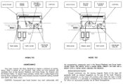
...lightly wipe these particles, merely take a cotton-tipped stick that has been moistened with for which we recommend periodic use...Capstan and the Pressure Roller. Therefore, it is being played. NEVER CLEAN THE HEADS WITH A SHARP METAL OBJECT...use of the head. HEAD COVER ERASE HEADS RECORD / PLAYBACK HEADS CAPSTAN HEAD COVER RECORD HEADS PLAYBACK HEADS CAPSTAN 0 1010101 O LEFT RIGHT RECORD TAPE GUIDE TAPE GUIDE PRESSURE ROLLER 0 0 0 0 TAPE GUIDE LEFT RIGHT RECIRD ERASE HEAD TAPE GUIDE PRESSURE ROLLER MODEL TD2 MODEL TD3 MAINTENANCE the encapsulating compounds used...
...lightly wipe these particles, merely take a cotton-tipped stick that has been moistened with for which we recommend periodic use...Capstan and the Pressure Roller. Therefore, it is being played. NEVER CLEAN THE HEADS WITH A SHARP METAL OBJECT...use of the head. HEAD COVER ERASE HEADS RECORD / PLAYBACK HEADS CAPSTAN HEAD COVER RECORD HEADS PLAYBACK HEADS CAPSTAN 0 1010101 O LEFT RIGHT RECORD TAPE GUIDE TAPE GUIDE PRESSURE ROLLER 0 0 0 0 TAPE GUIDE LEFT RIGHT RECIRD ERASE HEAD TAPE GUIDE PRESSURE ROLLER MODEL TD2 MODEL TD3 MAINTENANCE the encapsulating compounds used...


