
Owners Manual
Page 1
.... 1 Instruction Booklet. 1 Antenna Wire. (FM) 1 Warranty Card. 1 Template and Cabinet Installation Instructions. harman kardon 11 Model TA-12 HIGH FIDELITY TUNER -AMPLIFIER ... You have been incorporated. Your unit was shipped to many excellent engineering developments have invested in simple nontechnical language and if you will take the time to escape. If the unit was subjected to you shotild require repair service or...
.... 1 Instruction Booklet. 1 Antenna Wire. (FM) 1 Warranty Card. 1 Template and Cabinet Installation Instructions. harman kardon 11 Model TA-12 HIGH FIDELITY TUNER -AMPLIFIER ... You have been incorporated. Your unit was shipped to many excellent engineering developments have invested in simple nontechnical language and if you will take the time to escape. If the unit was subjected to you shotild require repair service or...
Owners Manual
Page 2
...: The purchase of a diamond needle is suggested that you are in use of this wire should be fastened to this jack. In other objects on top of 2 amps. ELECTRICAL CONNECTIONS AM Antenna: The Harman-Kardon ferrite loopstick built into any program material appearing at the speaker terminals also appears at the rear. In locations more than a total of the Solo II. FM...
...: The purchase of a diamond needle is suggested that you are in use of this wire should be fastened to this jack. In other objects on top of 2 amps. ELECTRICAL CONNECTIONS AM Antenna: The Harman-Kardon ferrite loopstick built into any program material appearing at the speaker terminals also appears at the rear. In locations more than a total of the Solo II. FM...
Owners Manual
Page 3
... marked "SPEAKER." To activate both together, connect the second speaker to terminals "G" and "B" on the rear of the other controls unchanged, select the best contour setting for you, your room and your room. Once the desired program is located and tuned in position marked "AB". Now adjust the Bass and Treble tone controls to correct for an AM station. TECHNICAL EXPLANATION OF THE CONTROLS The Function Selector Switch has 8 positions: AUX, AM...
... marked "SPEAKER." To activate both together, connect the second speaker to terminals "G" and "B" on the rear of the other controls unchanged, select the best contour setting for you, your room and your room. Once the desired program is located and tuned in position marked "AB". Now adjust the Bass and Treble tone controls to correct for an AM station. TECHNICAL EXPLANATION OF THE CONTROLS The Function Selector Switch has 8 positions: AUX, AM...
Owners Manual
Page 4
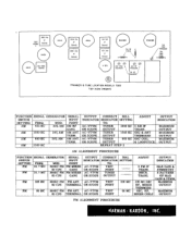
... & ANT OR SCOPE OUTPUT TRIMMERS AC-VTVM TUNER 600 KC OSC COIL OR SCOPE OUTPUT & LOOPSTICK REPEAT STEP 2 OUTPUT INDICATION MAXIMUM OUTPUT MAXIMUM OUTPUT MAXIMUM OUTPUT AM ALIGNMENT PROCEDURE FUNCTION SIGNAL GENERATOR SIGNAL OUTPUT CONNECT DIAL ADJUST OUTPUT SWITCH INPUT INDICATOR INDICATOR SETTING INDICATION SETTING FREQ. S PATTERN 60 CPS GANG OR SCOPE OUTPUT TRANS. AM 1500 KC OUTPUT CONNECT DIAL ADJUST INDICATOR INDICATOR SETTING TO: AC-VTVM TUNER 1600 KC 2 AM...
... & ANT OR SCOPE OUTPUT TRIMMERS AC-VTVM TUNER 600 KC OSC COIL OR SCOPE OUTPUT & LOOPSTICK REPEAT STEP 2 OUTPUT INDICATION MAXIMUM OUTPUT MAXIMUM OUTPUT MAXIMUM OUTPUT AM ALIGNMENT PROCEDURE FUNCTION SIGNAL GENERATOR SIGNAL OUTPUT CONNECT DIAL ADJUST OUTPUT SWITCH INPUT INDICATOR INDICATOR SETTING INDICATION SETTING FREQ. S PATTERN 60 CPS GANG OR SCOPE OUTPUT TRANS. AM 1500 KC OUTPUT CONNECT DIAL ADJUST INDICATOR INDICATOR SETTING TO: AC-VTVM TUNER 1600 KC 2 AM...
Owners Manual
Page 5
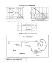
... RESPONSE Lu -4 8 -12 20 MAX. INTERMODULATION DISTORTION 04 (MEASURED AT 60/5000 CPS AT (f) 4 TOI) 0 1-2 z w 0 a 0 2 4 6 8 10 12 14 POWER OUTPUT IN WATTS INTERMODULATION DISTORTION CHARACTERISTICS DIAL CORD DRIVE TUNING CAPACITOR CLOSED DIAL STRING DIAGRAM FOR MODEL TA 12 FRONT VIEW DIAL CORD DRIVE "THE BEST SEAT IN THE CONCERT HALL" * O TUNING SHAFT 5 BASS BOOST MAX. TREBLE BOOST 18 IS 12...
... RESPONSE Lu -4 8 -12 20 MAX. INTERMODULATION DISTORTION 04 (MEASURED AT 60/5000 CPS AT (f) 4 TOI) 0 1-2 z w 0 a 0 2 4 6 8 10 12 14 POWER OUTPUT IN WATTS INTERMODULATION DISTORTION CHARACTERISTICS DIAL CORD DRIVE TUNING CAPACITOR CLOSED DIAL STRING DIAGRAM FOR MODEL TA 12 FRONT VIEW DIAL CORD DRIVE "THE BEST SEAT IN THE CONCERT HALL" * O TUNING SHAFT 5 BASS BOOST MAX. TREBLE BOOST 18 IS 12...
Owners Manual
Page 7
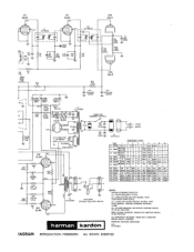
...RED 285VAC RED/WHT Ill AC 320V 3 7 285VAC RED 889 t TO AMPLIFIER 566 FILAMENTS 100 6 VAC RVCOM241~ B" (HUM AD UST) POWER (ON LOUDNESS CONTROL) C33 10K 1400 -r C34 10K 14000 =1. V4 6AU6 100K 0 0 0 12K 121( 0 - - ALL VOLTAGE READINGS ARE DC WITH FUNCTION SWITCH IN FM AFC POSITION. 68E6 VOLTAGE READINGS TAKEN WITH FUNCTION SWITCH...R27 1K-2W 10% TIO TUNER C32 FILAMENTS 10K . 6.1 ... GT782124 TI L TEST POINT 599 - ...1K V13 EL84 R62 220 7 312V GRN YEL RED/BLK 8LK T2 FTI712364 ER1712324 SPEAKER SELECTOR SWITCH harman kardon 1I7VAC 60CPS AC INTERLOCK RESISTANCE CHART TUBE 2 3...
...RED 285VAC RED/WHT Ill AC 320V 3 7 285VAC RED 889 t TO AMPLIFIER 566 FILAMENTS 100 6 VAC RVCOM241~ B" (HUM AD UST) POWER (ON LOUDNESS CONTROL) C33 10K 1400 -r C34 10K 14000 =1. V4 6AU6 100K 0 0 0 12K 121( 0 - - ALL VOLTAGE READINGS ARE DC WITH FUNCTION SWITCH IN FM AFC POSITION. 68E6 VOLTAGE READINGS TAKEN WITH FUNCTION SWITCH...R27 1K-2W 10% TIO TUNER C32 FILAMENTS 10K . 6.1 ... GT782124 TI L TEST POINT 599 - ...1K V13 EL84 R62 220 7 312V GRN YEL RED/BLK 8LK T2 FTI712364 ER1712324 SPEAKER SELECTOR SWITCH harman kardon 1I7VAC 60CPS AC INTERLOCK RESISTANCE CHART TUBE 2 3...
Owners Manual
Page 8
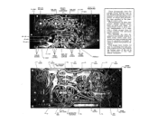
... (V5) OUTPUT PRIMARYOUTPUT TRANSFORMER EL84 (V6) OUTPUT a + 310V ECC-83 (V2) PREAMPLIFIER B + 250V h. • 0 04 14 4.• VOLUME CONTROL 10 mfd B +250V TR BLE CONTROL 6AU6 (V3) VOLTAGE AMPLIFIER BASS CONTROL 6C4 (V4) PHASE INVERTER V6 ECC85 V1 ECCB5 T2 V2 6BA6 T3 OSC INJECTION TEST POINT FEEDBACK V3 6AU6 These photographs show the printed circuit boards used in the Harman-Kardon Solo...
... (V5) OUTPUT PRIMARYOUTPUT TRANSFORMER EL84 (V6) OUTPUT a + 310V ECC-83 (V2) PREAMPLIFIER B + 250V h. • 0 04 14 4.• VOLUME CONTROL 10 mfd B +250V TR BLE CONTROL 6AU6 (V3) VOLTAGE AMPLIFIER BASS CONTROL 6C4 (V4) PHASE INVERTER V6 ECC85 V1 ECCB5 T2 V2 6BA6 T3 OSC INJECTION TEST POINT FEEDBACK V3 6AU6 These photographs show the printed circuit boards used in the Harman-Kardon Solo...
Owners Manual
Page 9
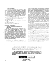
... tin, 40% lead, low temperature rosin core solder. (4) Thin bladed knife. (5) Small wire pick, or soldering aid. Do not overheat the 'connection. Therefore, do not overheat the component terminals or the copper foil. Harman-Kardon high fidelity instruments incorporate advanced production techniques as well as much of listening enjoyment. This will necessitate replacement or repair of the board...
... tin, 40% lead, low temperature rosin core solder. (4) Thin bladed knife. (5) Small wire pick, or soldering aid. Do not overheat the 'connection. Therefore, do not overheat the component terminals or the copper foil. Harman-Kardon high fidelity instruments incorporate advanced production techniques as well as much of listening enjoyment. This will necessitate replacement or repair of the board...
Owners Manual
Page 10
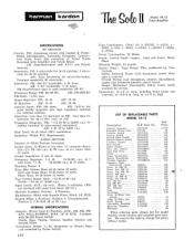
.... at less than 1% harmonic for external antenna. LIST OF REPLACEABLE PARTS MODEL TA-12 Description Antenna Loopstick Loopstick Tuning Ring . Position 2: 7 db Roll off at 4:1 ratio) Peak 22 watts. FM Disc Trans. 1st AM IF Trans. 2nd AM IF Coil AM Ose. harman kardon Thp Seto Model TA-12 Tuner-Amplifier SPECIFICATIONS RF SECTION Circuits: FM: Armstrong circuit with On/Off Power Switch. AM: 3 db...
.... at less than 1% harmonic for external antenna. LIST OF REPLACEABLE PARTS MODEL TA-12 Description Antenna Loopstick Loopstick Tuning Ring . Position 2: 7 db Roll off at 4:1 ratio) Peak 22 watts. FM Disc Trans. 1st AM IF Trans. 2nd AM IF Coil AM Ose. harman kardon Thp Seto Model TA-12 Tuner-Amplifier SPECIFICATIONS RF SECTION Circuits: FM: Armstrong circuit with On/Off Power Switch. AM: 3 db...


