
Owners Manual
Page 1
harman kardon The Award Series INSTALLATION AND OPERATING MANUAL MODEL T300X AM/FM INTEGRATED STEREO MULTIPLEX TUNER
harman kardon The Award Series INSTALLATION AND OPERATING MANUAL MODEL T300X AM/FM INTEGRATED STEREO MULTIPLEX TUNER
Owners Manual
Page 2
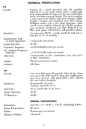
... db. TECHNICAL SPECIFICATIONS FM Circuit: Sensitivity: Discriminator Peak To Peak Separation: Image Rejection: Frequency Response: MX Adapter Frequency Response: Distortion: Limiter: Antenna: Consists of quieting.) 1 megacycle, ultra linear. 45 DB. ±-1 db 10-35,000 cycles per second. ±1 db 15-15,000 cycles per meter. Gated beam constant output. 300 ohms. AM Circuits: Sensitivity: Selectivity: Image Rejection...
... db. TECHNICAL SPECIFICATIONS FM Circuit: Sensitivity: Discriminator Peak To Peak Separation: Image Rejection: Frequency Response: MX Adapter Frequency Response: Distortion: Limiter: Antenna: Consists of quieting.) 1 megacycle, ultra linear. 45 DB. ±-1 db 10-35,000 cycles per second. ±1 db 15-15,000 cycles per meter. Gated beam constant output. 300 ohms. AM Circuits: Sensitivity: Selectivity: Image Rejection...
Owners Manual
Page 3
...performance from your T300X tuner. They also anticipate all of perfection itself. The keynote in the Award Series is essential you should be able to read this manual may save ...instruction manual carefully before found in the design of extensive research and experimentation in high fidelity component design. This booklet has been written in simple, non-technical language and by including features never before installing your stereophonic system. KEEP THIS BOOKLET AVAILABLE AT ALL TIMES FOR IT CONTAINS INDISPENSABLE TECHNICAL AND SERVICE INFORMATION. 3 INTRODUCTION The new Harman...
...performance from your T300X tuner. They also anticipate all of perfection itself. The keynote in the Award Series is essential you should be able to read this manual may save ...instruction manual carefully before found in the design of extensive research and experimentation in high fidelity component design. This booklet has been written in simple, non-technical language and by including features never before installing your stereophonic system. KEEP THIS BOOKLET AVAILABLE AT ALL TIMES FOR IT CONTAINS INDISPENSABLE TECHNICAL AND SERVICE INFORMATION. 3 INTRODUCTION The new Harman...
Owners Manual
Page 4
... the factory without delay to protect your rights under normal use and service, and in connection with the sale of this warranty apply to any part or parts, with the conditions herein below set be then shipped via Railway Express, Prepaid to fill in perfect operating condition. UNPACKING After unpacking the T300X, inspect it carefully for signs of our authorized warranty stations...
... the factory without delay to protect your rights under normal use and service, and in connection with the sale of this warranty apply to any part or parts, with the conditions herein below set be then shipped via Railway Express, Prepaid to fill in perfect operating condition. UNPACKING After unpacking the T300X, inspect it carefully for signs of our authorized warranty stations...
Owners Manual
Page 5
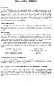
... must be used to connect the T300X tuner to your stereo amplifier. An AC convenience receptacle is located on /off switch. This connection will result in a manner to determine cable type. The heat generated by the on the rear of tuner components. Audio Output: Two AUDIO OUTPUT receptacles are used for either monophonic output receptacle and the TUNER or AUX input of the chassis. A third output receptacle located near the two audio outputs provides a multiplex...
... must be used to connect the T300X tuner to your stereo amplifier. An AC convenience receptacle is located on /off switch. This connection will result in a manner to determine cable type. The heat generated by the on the rear of tuner components. Audio Output: Two AUDIO OUTPUT receptacles are used for either monophonic output receptacle and the TUNER or AUX input of the chassis. A third output receptacle located near the two audio outputs provides a multiplex...
Owners Manual
Page 6
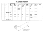
DIAL SETTING 455 KC 400 CPS Pin 2 ECH 81 AC VTVM at output jack 1600 KC 2 OSC 600 KC 400 CPS Couple signal same loosely by loop around loopstick 600 KC 3 OSC 1400 KC 400 CPS same same 1400 KC 4 Repeat steps 2 and 3. Trimmer ADJUST FOR Maximum ...Antenna Trimmer Maximum RF Trimmer 7 Repeat steps 5 and 6. L•10334•A ADJUST 1st, 2nd AM IF Trans. NOTES THE TUNING CAPACITOR PLATES MUST BE IN FULLY CLOSED POSITION (COUNTER CLOCKWISE ROTATION OF SHAFT I BEFORE ATTEMPTING TO STRING DIAL CORD. Use lowest input signal for usable indication. GENERATOR SETTING ...
DIAL SETTING 455 KC 400 CPS Pin 2 ECH 81 AC VTVM at output jack 1600 KC 2 OSC 600 KC 400 CPS Couple signal same loosely by loop around loopstick 600 KC 3 OSC 1400 KC 400 CPS same same 1400 KC 4 Repeat steps 2 and 3. Trimmer ADJUST FOR Maximum ...Antenna Trimmer Maximum RF Trimmer 7 Repeat steps 5 and 6. L•10334•A ADJUST 1st, 2nd AM IF Trans. NOTES THE TUNING CAPACITOR PLATES MUST BE IN FULLY CLOSED POSITION (COUNTER CLOCKWISE ROTATION OF SHAFT I BEFORE ATTEMPTING TO STRING DIAL CORD. Use lowest input signal for usable indication. GENERATOR SETTING ...
Owners Manual
Page 7
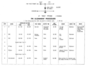
... note OUTPUT IND. Trimmer ADJUST FOR NOTES Maximum Remove ECC85 tube shield. Turn tuning gang fully CCW. Maximum Maximum 5 RF Amp 6 RFikrtip 7 90 MC 60 CPS 106 MC 60 CPS Repeat steps 5 and 6. Antenna Terminals Same Same Same 90 MC 106 MC Osc. FM TEST POINT ...2ppF CHASSIS 47K IN87, IN34, OR EOUIV, SCOPE STEP ALIGN. 1 IF IF TEST PROBE L4185362 FM ALIGNMENT PROCEDURE 1. Set pointer at Output 106 MC Adjust...
... note OUTPUT IND. Trimmer ADJUST FOR NOTES Maximum Remove ECC85 tube shield. Turn tuning gang fully CCW. Maximum Maximum 5 RF Amp 6 RFikrtip 7 90 MC 60 CPS 106 MC 60 CPS Repeat steps 5 and 6. Antenna Terminals Same Same Same 90 MC 106 MC Osc. FM TEST POINT ...2ppF CHASSIS 47K IN87, IN34, OR EOUIV, SCOPE STEP ALIGN. 1 IF IF TEST PROBE L4185362 FM ALIGNMENT PROCEDURE 1. Set pointer at Output 106 MC Adjust...

Owners Manual
Page 9
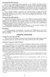
MODE SWITCH ,N M-FM POSITION, SELECTOR SWITCH IN FM POSITION. AFC SWITCH... AUTOMATIC FREQUENCY CONTROL IS 16 5V MP ADAPTER SOCKET 6.3V AO Px MODE SCOM ...33K .2.8K I .5K .49K .I.6K *270K .22K 33K *I FM IF TEST POINT X X GT2503045 V6 6B N6 240V MULTIPLEX OUTPUT C 2. X X - 1 GT2503045 C2 7 ' 470' K V5 6EO7 ...20V 6 95V 02 X GT2503051 P0781599 7 7 26 I .OK '40 VOLTAGE Et RESISTANCE READINGS AC OFF. K RESISTANCE READINGS MARKED WITH ASTERISK ARE MEASURED TO PIN S SCALA / EESI LEFT RIGHT STEREO MULTIPLEX (MONOPHONIC USE...
MODE SWITCH ,N M-FM POSITION, SELECTOR SWITCH IN FM POSITION. AFC SWITCH... AUTOMATIC FREQUENCY CONTROL IS 16 5V MP ADAPTER SOCKET 6.3V AO Px MODE SCOM ...33K .2.8K I .5K .49K .I.6K *270K .22K 33K *I FM IF TEST POINT X X GT2503045 V6 6B N6 240V MULTIPLEX OUTPUT C 2. X X - 1 GT2503045 C2 7 ' 470' K V5 6EO7 ...20V 6 95V 02 X GT2503051 P0781599 7 7 26 I .OK '40 VOLTAGE Et RESISTANCE READINGS AC OFF. K RESISTANCE READINGS MARKED WITH ASTERISK ARE MEASURED TO PIN S SCALA / EESI LEFT RIGHT STEREO MULTIPLEX (MONOPHONIC USE...
Owners Manual
Page 10
At times a TV antenna may be extended horizontally and tacked or stapled into place. OPERATING INSTRUCTIONS Turning The Tuner On and Off: The power on/off switch is distorted. Automatic Frequency Control Switch: FM broadcasting, by its job. It should consist of a single wire, as long as is not accurately done. Detune the station slightly so that the sound is located on the rear panel. The AFC...
At times a TV antenna may be extended horizontally and tacked or stapled into place. OPERATING INSTRUCTIONS Turning The Tuner On and Off: The power on/off switch is distorted. Automatic Frequency Control Switch: FM broadcasting, by its job. It should consist of a single wire, as long as is not accurately done. Detune the station slightly so that the sound is located on the rear panel. The AFC...
Owners Manual
Page 11
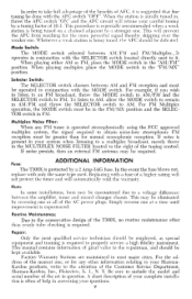
... the model and serial number of the set in question. Factory Warranty Stations are maintained in FM. Be sure to the conservative design of the AC power plugs. It operates in AM/FM and throw the SELECTOR switch to properly service a high fidelity instrument. Simply reverse one or all of the T300X, no routine maintenance other information relating to your HarmanKardon products, write...
... the model and serial number of the set in question. Factory Warranty Stations are maintained in FM. Be sure to the conservative design of the AC power plugs. It operates in AM/FM and throw the SELECTOR switch to properly service a high fidelity instrument. Simply reverse one or all of the T300X, no routine maintenance other information relating to your HarmanKardon products, write...
Owners Manual
Page 12
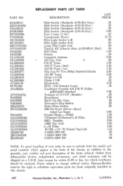
... the chassis, in this chassis. 460 Harman-Kardon, Inc., Plainview, L. Lamp Pilot Light *44 Tipjack, EF Johnson Minn *105-682-6 (Red) Dial Glass Pointer Loopstick Antenna AM Osc. IN542 5 Element M Derived L-R Filter 38KC Doubler 19KC Osc. PART NO. Prices subject to change without notice. Gray Decorative Plug Button Noise Fliter Switch 50K Pot Screw Driver-Knurl Adust Lin Taper Crystal Diode - ES4185313...
... the chassis, in this chassis. 460 Harman-Kardon, Inc., Plainview, L. Lamp Pilot Light *44 Tipjack, EF Johnson Minn *105-682-6 (Red) Dial Glass Pointer Loopstick Antenna AM Osc. IN542 5 Element M Derived L-R Filter 38KC Doubler 19KC Osc. PART NO. Prices subject to change without notice. Gray Decorative Plug Button Noise Fliter Switch 50K Pot Screw Driver-Knurl Adust Lin Taper Crystal Diode - ES4185313...


