

Owners Manual
Page 1
nee ti ..••4 ti ITY INT GRATED AMPLIFIER. *Whet s tilisa ::-:::-::::EEE • 1: • +.c%%'" •• its %).• •: 11 Miner ;A1.1 t)llt • .• ifllf Al . 11';'•! :-I..
nee ti ..••4 ti ITY INT GRATED AMPLIFIER. *Whet s tilisa ::-:::-::::EEE • 1: • +.c%%'" •• its %).• •: 11 Miner ;A1.1 t)llt • .• ifllf Al . 11';'•! :-I..
Owners Manual
Page 2
NO USER-SERVICEABLE PARTS INSIDE. WARNING: TO PREVENT FIRE OR SHOCK HAZARD, DO NOT EXPOSE THIS APPLIANCE TO RAIN OR MOISTURE. Contents Features General Instructions Locations for Installation Components and Their Functions Connections Operation Procedures Special Feature and Operation Maintenance 3 3 3 4 - 6 7 8,9 10,11 11 Indice Caratteristiche Istruzioni generali Posizioni per l ' installazione I componenti e le loro funzioni Collegamenti Procedimenti nell'operazione Caratteristiche e operazioni...
NO USER-SERVICEABLE PARTS INSIDE. WARNING: TO PREVENT FIRE OR SHOCK HAZARD, DO NOT EXPOSE THIS APPLIANCE TO RAIN OR MOISTURE. Contents Features General Instructions Locations for Installation Components and Their Functions Connections Operation Procedures Special Feature and Operation Maintenance 3 3 3 4 - 6 7 8,9 10,11 11 Indice Caratteristiche Istruzioni generali Posizioni per l ' installazione I componenti e le loro funzioni Collegamenti Procedimenti nell'operazione Caratteristiche e operazioni...

Owners Manual
Page 3
... trouble. Select a firm level base. When water or a metal piece enters the unit When water, a hair pin or wire accidentally enters the unit, immediately extract the AC plug from the outlet before making connections with internal components for inspection or maintenance. ce6isa, Locations for Installation *Always disconnect the plug from the outlet to prevent fire. General Instructions Always use of low-impedance, low...
... trouble. Select a firm level base. When water or a metal piece enters the unit When water, a hair pin or wire accidentally enters the unit, immediately extract the AC plug from the outlet before making connections with internal components for inspection or maintenance. ce6isa, Locations for Installation *Always disconnect the plug from the outlet to prevent fire. General Instructions Always use of low-impedance, low...

Owners Manual
Page 4
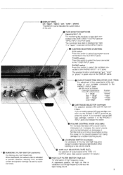
... balance adjustment between left channel signals. 4 )a Turn it clockwise for emphasis, or counterclockwise for a monaural source program. Components and Their Functions STEREO HEADPHONES JACK (headphones) For connection of low-pitched tone. SPEAKER SELECTORS (speakers 1, speakers 2) For selection of high-pitched tone. STEREO position: Select this jack. POWER SWITCH (POWER) For power on " in red color. Normally place it clockwise for emphasis, or counterclockwise for stereo playback, reception or recording. To sound both speaker systems, depress both switches. fL BASS CONTROL...
... balance adjustment between left channel signals. 4 )a Turn it clockwise for emphasis, or counterclockwise for a monaural source program. Components and Their Functions STEREO HEADPHONES JACK (headphones) For connection of low-pitched tone. SPEAKER SELECTORS (speakers 1, speakers 2) For selection of high-pitched tone. STEREO position: Select this jack. POWER SWITCH (POWER) For power on " in red color. Normally place it clockwise for emphasis, or counterclockwise for stereo playback, reception or recording. To sound both speaker systems, depress both switches. fL BASS CONTROL...
Owners Manual
Page 5
... "aux", "tuner" or "phone" in red color on to the TUNER INPUT jacks. PHONO switch : Press this switch to select the tuner connected to prevent speaker from turntable rumble and speaker damage caused by a sudden booming sound. itr) TAPE MONITOR SWITCHES (tape monitor 1, 2) For monitoring the equalizer or tape deck connected to cut filter is indicated as "tape 1" or "tape 2" in green color on the DISPLAY panel. Set this switch to select the program source connected to the PHONO 1 INPUT jacks...
... "aux", "tuner" or "phone" in red color on to the TUNER INPUT jacks. PHONO switch : Press this switch to select the tuner connected to prevent speaker from turntable rumble and speaker damage caused by a sudden booming sound. itr) TAPE MONITOR SWITCHES (tape monitor 1, 2) For monitoring the equalizer or tape deck connected to cut filter is indicated as "tape 1" or "tape 2" in green color on the DISPLAY panel. Set this switch to select the program source connected to the PHONO 1 INPUT jacks...
Owners Manual
Page 6
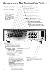
.... 22 TUNER INPUT JACKS (INPUT TUNER) Connect the output cables from your tuner here. 23 AUX INPUT JACKS (INPUT AUX) Connect the output cables from your turntable here. TAPE 2 OUTPUT JACKS (TAPE 2 OUT) Connect the input cables to your tape deck or equalizer here. 2 TAPE 2 INPUT JACKS (TAPE 2 IN) Connect the output cables from your turntable using either PHONO 1 or PHONO 2 INPUT jacks, please insert the attached SHORTING PLUGS into the PHONO INPUT jacks not in use. Components and Their Functions (Rear Panel) e GROUND TERMINAL (GND) Connect the grounding cable from...
.... 22 TUNER INPUT JACKS (INPUT TUNER) Connect the output cables from your tuner here. 23 AUX INPUT JACKS (INPUT AUX) Connect the output cables from your turntable here. TAPE 2 OUTPUT JACKS (TAPE 2 OUT) Connect the input cables to your tape deck or equalizer here. 2 TAPE 2 INPUT JACKS (TAPE 2 IN) Connect the output cables from your turntable using either PHONO 1 or PHONO 2 INPUT jacks, please insert the attached SHORTING PLUGS into the PHONO INPUT jacks not in use. Components and Their Functions (Rear Panel) e GROUND TERMINAL (GND) Connect the grounding cable from...
Owners Manual
Page 7
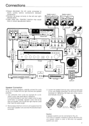
...) PHONO1 PHONO 2 * 0= r) 0 L AC OUTLET 0 0 u 0 R0 0 GND ®- 00000 HO • • TUNER eL r4=, OR 1 OUTPUT eL II= OR 1 = 1 I AC OUTLET Speaker Connection When connecting speakers, carefully connect the cords so as possible, and the left and rigfht channel jacks. • Insert plugs fully. Imperfect insertion may cause noise or sound reproduction failure. It is used, or 8t1 when two speaker systems are used. 7 Insert...
...) PHONO1 PHONO 2 * 0= r) 0 L AC OUTLET 0 0 u 0 R0 0 GND ®- 00000 HO • • TUNER eL r4=, OR 1 OUTPUT eL II= OR 1 = 1 I AC OUTLET Speaker Connection When connecting speakers, carefully connect the cords so as possible, and the left and rigfht channel jacks. • Insert plugs fully. Imperfect insertion may cause noise or sound reproduction failure. It is used, or 8t1 when two speaker systems are used. 7 Insert...
Owners Manual
Page 8
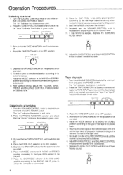
... position. 9. tape monitor 1 2 FFUNCTION-i aux tuner phono photo E]E]ElEini 3. TRIM knob at the proper position according to which the playing tape deck is placed at its OFF position. Gradually turn the VOLUME CONTROL knob until the desired tone is connected. 8 Tape playback 1. Adjust the BASS, TREBLE and BALANCE CONTROL knobs to the minimum level and press the POWER switch The "on the selected tape deck and set the tape...
... position. 9. tape monitor 1 2 FFUNCTION-i aux tuner phono photo E]E]ElEini 3. TRIM knob at the proper position according to which the playing tape deck is placed at its OFF position. Gradually turn the VOLUME CONTROL knob until the desired tone is connected. 8 Tape playback 1. Adjust the BASS, TREBLE and BALANCE CONTROL knobs to the minimum level and press the POWER switch The "on the selected tape deck and set the tape...
Owners Manual
Page 9
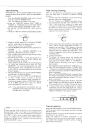
..." indicator on the DISPLAY panel illuminates, and the tape deck connected to 2 • SOUrCe tuner 3. TAPE OUT lax-2 to 1 off and press the TAPE MONITOR 2 switch. This adjustment does not affect the dubbing sound. 6. tone monitor 1 2 nFUNCT ION aux tuner phono o e When both the TAPE MONITOR 1 and 2 switches are pressed, both the TAPE MONITOR 1 and 2, switches off . 4. Recording has started . 5. While monitoring the sound, adjust the BASS, TREBLE and BALANCE controls as desired. Tape copying...
..." indicator on the DISPLAY panel illuminates, and the tape deck connected to 2 • SOUrCe tuner 3. TAPE OUT lax-2 to 1 off and press the TAPE MONITOR 2 switch. This adjustment does not affect the dubbing sound. 6. tone monitor 1 2 nFUNCT ION aux tuner phono o e When both the TAPE MONITOR 1 and 2 switches are pressed, both the TAPE MONITOR 1 and 2, switches off . 4. Recording has started . 5. While monitoring the sound, adjust the BASS, TREBLE and BALANCE controls as desired. Tape copying...

Owners Manual
Page 10
... 1 /2 OUTPUT jacks. Connection 5 13:11=1 Cassette deck IN OUT 0a To use of this unit allows connection with the TAPE MONITOR switches OFF, you can enjoy the selected source sound while copying the tape (dubbing). To monitor the source tape sound, press the TAPE MONITOR 2 switch. TAPE OUT off status when listening to a tuner, turntable or an auxiliary component connected to the AUX, INPUT jacks of an equalizer and operation instructions for...
... 1 /2 OUTPUT jacks. Connection 5 13:11=1 Cassette deck IN OUT 0a To use of this unit allows connection with the TAPE MONITOR switches OFF, you can enjoy the selected source sound while copying the tape (dubbing). To monitor the source tape sound, press the TAPE MONITOR 2 switch. TAPE OUT off status when listening to a tuner, turntable or an auxiliary component connected to the AUX, INPUT jacks of an equalizer and operation instructions for...
Owners Manual
Page 11
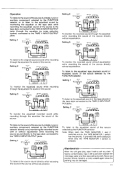
... connected to the TAPE 2 INPUT/OUTPUT jacks through the equalizer the sound of the source. Never use alcohol, thinner, benzine or other volatile agent since the painting may be damaged. 11 rce tuner 1 p„" rkFUNCTION r aker System 0 0 °aside,. Note: When both the TAPE MONITOR 1 and 2 switches are on the tape deck connected to ' L-„e2b:r Spea lei 0 0 .P.r.°T 1rEir ,SUNCTiOaln 1 aux tone. Setting...
... connected to the TAPE 2 INPUT/OUTPUT jacks through the equalizer the sound of the source. Never use alcohol, thinner, benzine or other volatile agent since the painting may be damaged. 11 rce tuner 1 p„" rkFUNCTION r aker System 0 0 °aside,. Note: When both the TAPE MONITOR 1 and 2 switches are on the tape deck connected to ' L-„e2b:r Spea lei 0 0 .P.r.°T 1rEir ,SUNCTiOaln 1 aux tone. Setting...


