

Owners Manual
Page 2
Table of contents WARRANTY AND SERVICE INTRODUCTION INSTALLATION CONNECTING SPEAKER SYSTEMS ANTENNA (FM AND AM) OPERATION SELECTING MONOPHONIC OR FM STEREO BROADCASTS RECORD CHANGER THE CASSETTE SERVICE AND MAINTENANCE REPLACEMENT PARTS LIST page 2 3 4 6 8 10 14 15 16 22 24 TT
Table of contents WARRANTY AND SERVICE INTRODUCTION INSTALLATION CONNECTING SPEAKER SYSTEMS ANTENNA (FM AND AM) OPERATION SELECTING MONOPHONIC OR FM STEREO BROADCASTS RECORD CHANGER THE CASSETTE SERVICE AND MAINTENANCE REPLACEMENT PARTS LIST page 2 3 4 6 8 10 14 15 16 22 24 TT

Owners Manual
Page 3
... forwarded to you . HARMAN-KARDON has a special customer service division to answer all other obligations or liabilities on our part, and we neither assume nor authorize any representative or other person to assume for us any other liability in connection with instructions furnished by us at any defective parts of the speakers charging only for "factory validation" within the...
... forwarded to you . HARMAN-KARDON has a special customer service division to answer all other obligations or liabilities on our part, and we neither assume nor authorize any representative or other person to assume for us any other liability in connection with instructions furnished by us at any defective parts of the speakers charging only for "factory validation" within the...

Owners Manual
Page 4
... installation and operation. Congratulations. It combines superb styling with a rich resonance that you are in a single stereo unit. Some time ago, Harman-Kardon, set is truly superb, vibrating with a performance level never before achieved in their own. the Festival Music System. Your speakers have multi-layer voice coils enabling them to dramatically fulfill the extraordinary promise of power. The bass response is switched...
... installation and operation. Congratulations. It combines superb styling with a rich resonance that you are in a single stereo unit. Some time ago, Harman-Kardon, set is truly superb, vibrating with a performance level never before achieved in their own. the Festival Music System. Your speakers have multi-layer voice coils enabling them to dramatically fulfill the extraordinary promise of power. The bass response is switched...
Owners Manual
Page 5
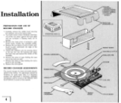
... = 1 OWNERS MANUAL 2 SPEAKER CABLES 1 MANUAL SPINDLE 1 AUTOMATIC SPINDLE PROTECTIVE CARDBOARD (2) TRANSIT SCREW TURNTABLE PLATTER STABILIZER ARM HOUSING w II TRANSIT SCREW TONE ARM TAPE STYLUS GUARD Turn both transit screws clockwise until they are all the way down at the factory. Carefully remove the rubber band securing the stabilizer arm to the cartridge. 8. No adjustment should be found in the SERVICE AND...
... = 1 OWNERS MANUAL 2 SPEAKER CABLES 1 MANUAL SPINDLE 1 AUTOMATIC SPINDLE PROTECTIVE CARDBOARD (2) TRANSIT SCREW TURNTABLE PLATTER STABILIZER ARM HOUSING w II TRANSIT SCREW TONE ARM TAPE STYLUS GUARD Turn both transit screws clockwise until they are all the way down at the factory. Carefully remove the rubber band securing the stabilizer arm to the cartridge. 8. No adjustment should be found in the SERVICE AND...
Owners Manual
Page 6
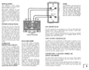
... three inches behind the control center when installing into any other high level program source such as power lines, transformers, or other electrical equipment. OVERLOAD PROTECTION CIRCUIT In the event of the function switch. If hum persists, reverse the AC power plug. Replacing with any outlet furnishing 117 volts, 60 hertz AC current. AUX RECEPTACLES The AUX receptacles are operated conservatively for use with a fuse of this...
... three inches behind the control center when installing into any other high level program source such as power lines, transformers, or other electrical equipment. OVERLOAD PROTECTION CIRCUIT In the event of the function switch. If hum persists, reverse the AC power plug. Replacing with any outlet furnishing 117 volts, 60 hertz AC current. AUX RECEPTACLES The AUX receptacles are operated conservatively for use with a fuse of this...
Owners Manual
Page 7
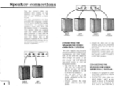
... molding for this instruction manual which indicate the exact location of the system. 5. Your music system is now connected for quick, trouble-free speaker connections. Similarly connect the other end of the speaker cable to your system with a phono plug connector at each end for an inconspicuous and neat installation. Plug one system) or four speakers (two systems) to the diagrams supplied in the "ON" position. CONNECTING THE SPEAKERS FOR STEREO OPERATION (2 SYSTEMS) 1.
... molding for this instruction manual which indicate the exact location of the system. 5. Your music system is now connected for quick, trouble-free speaker connections. Similarly connect the other end of the speaker cable to your system with a phono plug connector at each end for an inconspicuous and neat installation. Plug one system) or four speakers (two systems) to the diagrams supplied in the "ON" position. CONNECTING THE SPEAKERS FOR STEREO OPERATION (2 SYSTEMS) 1.

Owners Manual
Page 8
.... The room diagrams will give you determine that your room layout and it is important. Since all rooms are properly phased. There should never be the impression of two separated sound sources, neither should be in solving a specific unusual room problem please write and include a simple drawing of your system will be out of phase. Place the FUNCTION switch in connections...
.... The room diagrams will give you determine that your room layout and it is important. Since all rooms are properly phased. There should never be the impression of two separated sound sources, neither should be in solving a specific unusual room problem please write and include a simple drawing of your system will be out of phase. Place the FUNCTION switch in connections...

Owners Manual
Page 9
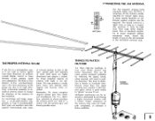
... using an external antenna connect both leads of the antenna wire to the two FM antenna terminal posts on the rear of your system the 48" wire supplied is improved, you use. Antenna (FM and AM) WATER TOWER TRANSMITTER CONNECTING THE FM ANTENNA Due to the exceptionally high sensitivity of your Music System. When using the antenna supplied connect one end of the 48" wire to the roof, chimney, wall...
... using an external antenna connect both leads of the antenna wire to the two FM antenna terminal posts on the rear of your system the 48" wire supplied is improved, you use. Antenna (FM and AM) WATER TOWER TRANSMITTER CONNECTING THE FM ANTENNA Due to the exceptionally high sensitivity of your Music System. When using the antenna supplied connect one end of the 48" wire to the roof, chimney, wall...
Owners Manual
Page 10
... you wish to receive signals from large metal objects, power lines or electrical machinery to -eight-element logperiodic or Yagi is usually quite heavy and requires extra support and bracing, when installed. This type antenna is recommended. Gas tanks? This form of a signal wire, as long as multipath interference (more remote locations an additional outdoor antenna may tune out...
... you wish to receive signals from large metal objects, power lines or electrical machinery to -eight-element logperiodic or Yagi is usually quite heavy and requires extra support and bracing, when installed. This type antenna is recommended. Gas tanks? This form of a signal wire, as long as multipath interference (more remote locations an additional outdoor antenna may tune out...
Owners Manual
Page 11
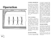
... volume level will increase, as compared to attain system balance. Any variation in the center or "flat" position. The controls provide a range of adjustment of one channel against the othei'. Since there may have a better understanding of any program material connected to your FESTIVAL 2 Music System has been designed to be set in cases where major unbalance exists. The normal operating...
... volume level will increase, as compared to attain system balance. Any variation in the center or "flat" position. The controls provide a range of adjustment of one channel against the othei'. Since there may have a better understanding of any program material connected to your FESTIVAL 2 Music System has been designed to be set in cases where major unbalance exists. The normal operating...
Owners Manual
Page 12
... at low listening levels, push the CONTOUR switch IN. When connecting 4 speakers to the System 1 & 2 speaker terminals, both speaker systems, may be used to the recording after the last record has played. TAPE PHONO AUX AUTO FM MONO FM AM 1111111111111111111111111111111 STATION TUNING TAPE MONITOR O CONTOUR O SPEAKER SYSTEM I O SPEAKER SYSTEM 2 Cs POWER ON O HEAD PHONES SOURCE OFF TT!!!!!!, OFF OFF AUTO OFF STEREO HEADPHONE RECEPTACLE The stereo headphone receptacle located on the front panel of...
... at low listening levels, push the CONTOUR switch IN. When connecting 4 speakers to the System 1 & 2 speaker terminals, both speaker systems, may be used to the recording after the last record has played. TAPE PHONO AUX AUTO FM MONO FM AM 1111111111111111111111111111111 STATION TUNING TAPE MONITOR O CONTOUR O SPEAKER SYSTEM I O SPEAKER SYSTEM 2 Cs POWER ON O HEAD PHONES SOURCE OFF TT!!!!!!, OFF OFF AUTO OFF STEREO HEADPHONE RECEPTACLE The stereo headphone receptacle located on the front panel of...
Owners Manual
Page 13
... frequency and when the record is played at the low and high ends of any high level program source, connected to make necessary adjustments for the limitations of the recording technique, record manufacturers have found it is the normal listening position for playback. 4. This recording curve has been incorporated in music and to the AUX input receptacles on "SELECTING MONOPHONIC OR STEREO...
... frequency and when the record is played at the low and high ends of any high level program source, connected to make necessary adjustments for the limitations of the recording technique, record manufacturers have found it is the normal listening position for playback. 4. This recording curve has been incorporated in music and to the AUX input receptacles on "SELECTING MONOPHONIC OR STEREO...

Owners Manual
Page 14
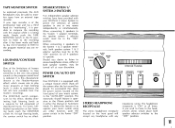
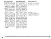
O -Er SOURCE OFF OFF OFF 41•1 111. AUTO OFF HEAD PHONES O 13 The AM and FM scales are illuminated to provide sharp illumination III of AM and FM stations. STATION TUNING SPEAKER SPEAKER POWER SYSTEM I STEREO PHONO AUX AUTO E FM MONO FM AM TAPE MONITOR O CONTOUR O 1110- DIAL SCALE Your FESTIVAL 2 utilizes a rotary dial scale to provide optimum visibility and can also provide optimum visibility and can also serve as an ON/OFF indicator for your FESTIVAL 2. 0 -FPM41111•11 0 AM 0 R MAX MIN I SYSTEM 2 ON - 6-
O -Er SOURCE OFF OFF OFF 41•1 111. AUTO OFF HEAD PHONES O 13 The AM and FM scales are illuminated to provide sharp illumination III of AM and FM stations. STATION TUNING SPEAKER SPEAKER POWER SYSTEM I STEREO PHONO AUX AUTO E FM MONO FM AM TAPE MONITOR O CONTOUR O 1110- DIAL SCALE Your FESTIVAL 2 utilizes a rotary dial scale to provide optimum visibility and can also provide optimum visibility and can also serve as an ON/OFF indicator for your FESTIVAL 2. 0 -FPM41111•11 0 AM 0 R MAX MIN I SYSTEM 2 ON - 6-

Owners Manual
Page 15
... the two patch cords connected to make use of operation. O AUX TAPE OUT ® ® R L 0 HARMAN KARDON INCORPORATED PLAINVIEW,N.Y. MODEL FESTIVAL 2 MADE IN U.S.A. 0 PREAMP 0 RI L&TT AMP G QUADRAPHONIC SERIAL NO. In order to these receptacles and follow the instructions supplied with a stereo sensing circuit which can automatically determine if your system will automatically switch back to monophonic reception. Should the station conclude broadcasting in the...
... the two patch cords connected to make use of operation. O AUX TAPE OUT ® ® R L 0 HARMAN KARDON INCORPORATED PLAINVIEW,N.Y. MODEL FESTIVAL 2 MADE IN U.S.A. 0 PREAMP 0 RI L&TT AMP G QUADRAPHONIC SERIAL NO. In order to these receptacles and follow the instructions supplied with a stereo sensing circuit which can automatically determine if your system will automatically switch back to monophonic reception. Should the station conclude broadcasting in the...
Owners Manual
Page 16
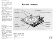
...center hole by rotating the spindle until the stylus enters the assigned groove. Stack up to revolve. 7. Set the control knobs for the correct record size and speed. 5. MANUAL SPINDLE STABILIZER ARM CUEING LEVER CONTROL KNOB (SPEED SELECTOR) TONE ARM LOCKING REST CONTROL KNOB 15 Using the cueing lever, raise the tone...positioning the stabilizer arm over the records. 4. AUTOMATIC PLAY 1. Slide the control knob from the OFF position to the right. 2. Lift the stabilizer arm and swing it there momentarily until the turntable starts to six records on the record. 7. Make ...
...center hole by rotating the spindle until the stylus enters the assigned groove. Stack up to revolve. 7. Set the control knobs for the correct record size and speed. 5. MANUAL SPINDLE STABILIZER ARM CUEING LEVER CONTROL KNOB (SPEED SELECTOR) TONE ARM LOCKING REST CONTROL KNOB 15 Using the cueing lever, raise the tone...positioning the stabilizer arm over the records. 4. AUTOMATIC PLAY 1. Slide the control knob from the OFF position to the right. 2. Lift the stabilizer arm and swing it there momentarily until the turntable starts to six records on the record. 7. Make ...

Owners Manual
Page 17
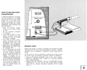
...protect against accidental erasure. Once you may have been removed on almost any magnetic fields (e.g., speaker magnets, transformers, or electric motors). Be sure the tab falls free from 0 to make your own recording on a table as a guide. NOTE: If at room temperature, away from any source...experience that you wish to protect either 60, 90, or 120 minutes of total playing time. If both sides of your pre-recorded cassette, or one ...side of the tape, appearing in the rear of the cassette housing. At the present time the program material recorded on any prerecorded tapes you...
...protect against accidental erasure. Once you may have been removed on almost any magnetic fields (e.g., speaker magnets, transformers, or electric motors). Be sure the tab falls free from 0 to make your own recording on a table as a guide. NOTE: If at room temperature, away from any source...experience that you wish to protect either 60, 90, or 120 minutes of total playing time. If both sides of your pre-recorded cassette, or one ...side of the tape, appearing in the rear of the cassette housing. At the present time the program material recorded on any prerecorded tapes you...

Owners Manual
Page 20
... LEVEL CONTROL The "RECORD LEVEL" control is used to adjust the incoming signal information to the proper recording level as an integral part of the "RECORD LEVEL" control. When recording monophonically, place one microphone in the "MONO-LEFT" microphone input receptacle and place the MONOSTEREO switch in the "STEREO" position. To turn the power off, merely rotate the control in a full counterclockwise direction. To turn the power on...
... LEVEL CONTROL The "RECORD LEVEL" control is used to adjust the incoming signal information to the proper recording level as an integral part of the "RECORD LEVEL" control. When recording monophonically, place one microphone in the "MONO-LEFT" microphone input receptacle and place the MONOSTEREO switch in the "STEREO" position. To turn the power off, merely rotate the control in a full counterclockwise direction. To turn the power on...

Owners Manual
Page 21
... necessary. 6. When the controls are properly set too high and your recording will be used without resetting the controls, (e.g., to record. 10. When the recording is now in a clockwise direction until the meter pointer deflects toward the red zone. Depress the "STOP/CASSETTE EJECT" button. Depress the PAUSE button again, to the desired listening level. 8. Turn the power for recording, depress the...
... necessary. 6. When the controls are properly set too high and your recording will be used without resetting the controls, (e.g., to record. 10. When the recording is now in a clockwise direction until the meter pointer deflects toward the red zone. Depress the "STOP/CASSETTE EJECT" button. Depress the PAUSE button again, to the desired listening level. 8. Turn the power for recording, depress the...
Owners Manual
Page 22
... #3 through #10. 6. Place the FUNCTION SELECTOR switch to its minimum position 7. Rotate the "RECORD LEVEL" control to the "AUX" position. Place the function selector MONO STEREO switch of your voice could vary in the process of the microphone input receptacles. 5. set and you are properly (full counterclockwise). OHMS). 1. When the controls are ready to AUX . MONO phonic recording, insert one microphone...
... #3 through #10. 6. Place the FUNCTION SELECTOR switch to its minimum position 7. Rotate the "RECORD LEVEL" control to the "AUX" position. Place the function selector MONO STEREO switch of your voice could vary in the process of the microphone input receptacles. 5. set and you are properly (full counterclockwise). OHMS). 1. When the controls are ready to AUX . MONO phonic recording, insert one microphone...
Owners Manual
Page 23
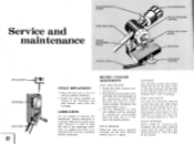
... tone arm floats in top operating condition, we suggest you have it inspected once a year by a qualified service technician. However, in the exact horizontal position. COUNTERWEIGHT SCREW TONE ARM TUBE Service and z maintenance HEIGHT ADJUSTMENT SCREW CUEING LEVER COUNTERWEIGHT STYLUS PRESSURE CONTROL STYLUS SET DOWN SCREW INDICATOR ANTI-SKATE CONTROL STYLUS ASS'Y CARTRIDGE It TONE ARM 22 I STYLUS REPLACEMENT 1. RECORD CHANGER ADJUSTMENTS TONE...
... tone arm floats in top operating condition, we suggest you have it inspected once a year by a qualified service technician. However, in the exact horizontal position. COUNTERWEIGHT SCREW TONE ARM TUBE Service and z maintenance HEIGHT ADJUSTMENT SCREW CUEING LEVER COUNTERWEIGHT STYLUS PRESSURE CONTROL STYLUS SET DOWN SCREW INDICATOR ANTI-SKATE CONTROL STYLUS ASS'Y CARTRIDGE It TONE ARM 22 I STYLUS REPLACEMENT 1. RECORD CHANGER ADJUSTMENTS TONE...

