

Owners Manual
Page 2
IMPORTANT Please read this manual carefully before installing and operating your new Citation B Stereo Power Amplifier. You have invested in a high quality electronic component and a few moments taken now to read this manual may save considerable time and effort later on. Keep this instruction manual readily available since it contains valuable technical and service information.
IMPORTANT Please read this manual carefully before installing and operating your new Citation B Stereo Power Amplifier. You have invested in a high quality electronic component and a few moments taken now to read this manual may save considerable time and effort later on. Keep this instruction manual readily available since it contains valuable technical and service information.
Owners Manual
Page 4
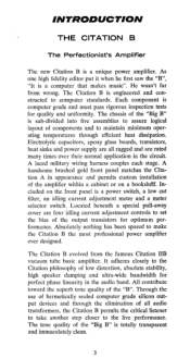
... a power switch, a low cut filter, an idling current adjustment meter and a meter selector switch. Electrolytic capacitors, epoxy glass boards, transistors, heat sinks and power supply are all audio transformers, the Citation B permits the critical listener to take another step closer to make the Citation B the most professional power amplifier ever designed. All contribute toward the superb tone quality of hermetically sealed computer grade silicon output...
... a power switch, a low cut filter, an idling current adjustment meter and a meter selector switch. Electrolytic capacitors, epoxy glass boards, transistors, heat sinks and power supply are all audio transformers, the Citation B permits the critical listener to take another step closer to make the Citation B the most professional power amplifier ever designed. All contribute toward the superb tone quality of hermetically sealed computer grade silicon output...
Owners Manual
Page 5
... sealed computer grade silicon output devices deliver exceptionally wide frequency response at full power output with low distortion. • Metered output circuit with idling current adjustments located on all types of speaker loads. better than 1 microsecond rise time. • Laced military wiring harness connects all stages. • Unconditional TWO YEAR service warranty on front panel. • Absolutely fail-safe operation with all parts including output transistors. 4
... sealed computer grade silicon output devices deliver exceptionally wide frequency response at full power output with low distortion. • Metered output circuit with idling current adjustments located on all types of speaker loads. better than 1 microsecond rise time. • Laced military wiring harness connects all stages. • Unconditional TWO YEAR service warranty on front panel. • Absolutely fail-safe operation with all parts including output transistors. 4
Owners Manual
Page 6
... SET BE SHIPPED DIRECTLY TO THE FACTORY WITHOUT PRIOR AUTHORIZATION. The Harman-Kardon warranty is expressly in our judgment to affect its stability or reliability nor which has been connected otherwise than in perfect operating condition. If the amplifier was subjected to the station designated, accompanied by the ON/OFF switch. 5 Neither shall this instrument. UNPACKING After unpacking the Citation...
... SET BE SHIPPED DIRECTLY TO THE FACTORY WITHOUT PRIOR AUTHORIZATION. The Harman-Kardon warranty is expressly in our judgment to affect its stability or reliability nor which has been connected otherwise than in perfect operating condition. If the amplifier was subjected to the station designated, accompanied by the ON/OFF switch. 5 Neither shall this instrument. UNPACKING After unpacking the Citation...
Owners Manual
Page 7
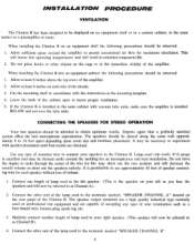
... installing the Citation B on professional test equipment and are obtained. Do not place books or other end of the lamp cord to insure proper ventilation. 5. Connect the other objects on the rear panel of the amplifier. Similarly connect another length of the cabinet open to the terminals marked, "SPEAKER CHANNEL A" located on the cage or in the same cabinet with the instructions...
... installing the Citation B on professional test equipment and are obtained. Do not place books or other end of the lamp cord to insure proper ventilation. 5. Connect the other objects on the rear panel of the amplifier. Similarly connect another length of the cabinet open to the terminals marked, "SPEAKER CHANNEL A" located on the cage or in the same cabinet with the instructions...
Owners Manual
Page 8
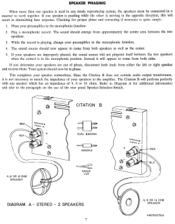
... contain audio output transformers, it will appear to the paragraph on the use of phase, disconnect both sides. C CITATION B C RED BLK SPEAKER CHAN ,,, DUAL BANANA L 3 4,8 OR 16 OHM SPEAKER BANANA SPADE LUG SPEAKER CHAN A RED BLK DIAGRAM A - Checking for additional information and also to come from both speakers as well as the center. 5. If you determine your speakers are out of the rear panel Speaker Selection Switch. If one speaker is used...
... contain audio output transformers, it will appear to the paragraph on the use of phase, disconnect both sides. C CITATION B C RED BLK SPEAKER CHAN ,,, DUAL BANANA L 3 4,8 OR 16 OHM SPEAKER BANANA SPADE LUG SPEAKER CHAN A RED BLK DIAGRAM A - Checking for additional information and also to come from both speakers as well as the center. 5. If you determine your speakers are out of the rear panel Speaker Selection Switch. If one speaker is used...
Owners Manual
Page 9
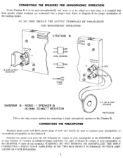
... (Channel A) output of your preamplifier to the Citation B. CONNECTING THE SPEAKERS FOR MONOPHONIC OPERATION If the Citation B is to be used monophonically and stereo is to be added at each end should be used to connect your monophonic or stereophonic preamplifier to the Citation B. I SPEAKER Ei 16 OHM 20 WATT RESISTOR 4, 8 OR 16 OHM SPEAKER 0 H90720168A This is the only correct method for proper installation of your amplifier...
... (Channel A) output of your preamplifier to the Citation B. CONNECTING THE SPEAKERS FOR MONOPHONIC OPERATION If the Citation B is to be used monophonically and stereo is to be added at each end should be used to connect your monophonic or stereophonic preamplifier to the Citation B. I SPEAKER Ei 16 OHM 20 WATT RESISTOR 4, 8 OR 16 OHM SPEAKER 0 H90720168A This is the only correct method for proper installation of your amplifier...
Owners Manual
Page 10
... power switch located on the rear chassis. SPEAKER SELECTOR SWITCH Although transistors do not require impedance matching, for any impedance. It turns the amplifier on /off without operating the Citation B power switch. This switch may now be connected to this switch to check and then readjust if necessary, the idling current of power output transistors. A difference in conjunction with this amplifier, use the special LOW CUT FILTER located on and off power switch...
... power switch located on the rear chassis. SPEAKER SELECTOR SWITCH Although transistors do not require impedance matching, for any impedance. It turns the amplifier on /off without operating the Citation B power switch. This switch may now be connected to this switch to check and then readjust if necessary, the idling current of power output transistors. A difference in conjunction with this amplifier, use the special LOW CUT FILTER located on and off power switch...
Owners Manual
Page 11
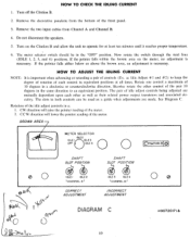
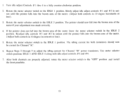
... panelette from Channel A and Channel B. 4. The meter selector switch should be used as their related power output transistors and associated circuitry. BROWN AREA O METER SELECTOR IDLE2 IDLE I IDLE 3 OFF IDLE 4 0 0 SHAFT SLOT POSIT/ON SHAFT SLOT POSITION IDLE I IDLE 2 LCflANN EL Al CORRECT ADJUSTMENT IDLE 3 IDLE 4 LCHANNEL INCORRECT ADJUSTMENT C i•rd:cri Ollt B O DIAGRAM C H9072017 I A Q 10 Rotate one control a maximum...
... panelette from Channel A and Channel B. 4. The meter selector switch should be used as their related power output transistors and associated circuitry. BROWN AREA O METER SELECTOR IDLE2 IDLE I IDLE 3 OFF IDLE 4 0 0 SHAFT SLOT POSIT/ON SHAFT SLOT POSITION IDLE I IDLE 2 LCflANN EL Al CORRECT ADJUSTMENT IDLE 3 IDLE 4 LCHANNEL INCORRECT ADJUSTMENT C i•rd:cri Ollt B O DIAGRAM C H9072017 I A Q 10 Rotate one control a maximum...
Owners Manual
Page 12
... "OFF" position and install the front panelette. 11 After both transistors should now fall into the brown area of the meter leave the meter selector switch in 10 degree increments or less) 3. Use meter selector switch positions IDLE 3 AND IDLE 4 along with idle adjust controls # 3 and #4. 7. The pointer should now be correct for Channel "B" power transistors. If the...
... "OFF" position and install the front panelette. 11 After both transistors should now fall into the brown area of the meter leave the meter selector switch in 10 degree increments or less) 3. Use meter selector switch positions IDLE 3 AND IDLE 4 along with idle adjust controls # 3 and #4. 7. The pointer should now be correct for Channel "B" power transistors. If the...
Owners Manual
Page 13
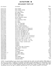
... a C.O.D. CITATION B REPLACEMENT PARTS LIST Part Number Description Price H24013764 H24018199 H24018200 H21518204 H65418213 H61217124 H46512117 H24018197 H65411919 H65416751 1153013678 H65420059 H45013202 H45012856 H65418195 H28018214 H28018260 H28018231 H31518185 H31518186 H31518176 H31518177 H31519980 H31518183 H36718178 H41015683 H41020180 H43019955 H43018082 H43018080 H43020158 H67018189 H85018259 H38019956 H10118188 H63018173 H12518207 --H63018175 H63216767 H63418224 H60118194 H90718257 Power Switch Meter Selector Switch Low Cut Switch Idle Adjust Control Banana Plug Pilot Light...
... a C.O.D. CITATION B REPLACEMENT PARTS LIST Part Number Description Price H24013764 H24018199 H24018200 H21518204 H65418213 H61217124 H46512117 H24018197 H65411919 H65416751 1153013678 H65420059 H45013202 H45012856 H65418195 H28018214 H28018260 H28018231 H31518185 H31518186 H31518176 H31518177 H31519980 H31518183 H36718178 H41015683 H41020180 H43019955 H43018082 H43018080 H43020158 H67018189 H85018259 H38019956 H10118188 H63018173 H12518207 --H63018175 H63216767 H63418224 H60118194 H90718257 Power Switch Meter Selector Switch Low Cut Switch Idle Adjust Control Banana Plug Pilot Light...


