User Guide
Page 1
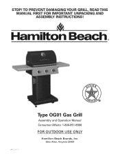
Glen Allen, Virginia 23060 TO PREVENT DAMAGING YOUR GRILL, READ THIS MANUAL FIRST FOR IMPORTANT UNPACKING AND ASSEMBLY INSTRUCTIONS! 840208101 DESIGN CERTIFIED Type OG01 Gas Grill Assembly and Operation Manual Consumer Affairs: 1-800-851-8900 FOR OUTDOOR USE ONLY Hamilton Beach Brands, Inc. STOP!
Glen Allen, Virginia 23060 TO PREVENT DAMAGING YOUR GRILL, READ THIS MANUAL FIRST FOR IMPORTANT UNPACKING AND ASSEMBLY INSTRUCTIONS! 840208101 DESIGN CERTIFIED Type OG01 Gas Grill Assembly and Operation Manual Consumer Affairs: 1-800-851-8900 FOR OUTDOOR USE ONLY Hamilton Beach Brands, Inc. STOP!

User Guide
Page 2
... gas to Our Users ...3 Safety Symbols ...3 Installation/Safety Precautions 4 Propane and Gas Warning ...4 Grill Parts List ...5 Grill Parts Diagram ...7 ASSEMBLY Before the Assembly ...8 Assembly Steps ...11 POST-ASSEMBLY Gas Connection ...19 Leak Testing ...23 Final Installation Checklist ...24 Grill Lighting Instruction ...24 Operating Instruction ...26 Safety Tips ...28 Care and Maintenance ...28 Troubleshooting...
... gas to Our Users ...3 Safety Symbols ...3 Installation/Safety Precautions 4 Propane and Gas Warning ...4 Grill Parts List ...5 Grill Parts Diagram ...7 ASSEMBLY Before the Assembly ...8 Assembly Steps ...11 POST-ASSEMBLY Gas Connection ...19 Leak Testing ...23 Final Installation Checklist ...24 Grill Lighting Instruction ...24 Operating Instruction ...26 Safety Tips ...28 Care and Maintenance ...28 Troubleshooting...
User Guide
Page 3
... of each of the symbols is not intended to them. NOTE TO INSTALLER: Leave this user's manual in its entirety before using the grill. • Please contact Consumer Affairs if you for future reference. This symbol indicates a hazardous situation which will enjoy using our fine products.... • Please read this grill may have sharp edges. BEFORE YOU BEGIN MESSAGE TO OUR USERS Thank you have any questions. • Please read this user's manual in...
... of each of the symbols is not intended to them. NOTE TO INSTALLER: Leave this user's manual in its entirety before using the grill. • Please contact Consumer Affairs if you for future reference. This symbol indicates a hazardous situation which will enjoy using our fine products.... • Please read this grill may have sharp edges. BEFORE YOU BEGIN MESSAGE TO OUR USERS Thank you have any questions. • Please read this user's manual in...
User Guide
Page 4
... hour) of this product. INSTALLATION/SAFETY PRECAUTIONS wWARNING READ THIS SECTION FIRST BEFORE INSTALLING THE GRILL • This grill is not responsible for LP gas tanks of the grill while in the United States and Canada only. Hamilton Beach is designed to use . • This grill is to cause cancer, birth defects, and other reproductive harm. 2.
... hour) of this product. INSTALLATION/SAFETY PRECAUTIONS wWARNING READ THIS SECTION FIRST BEFORE INSTALLING THE GRILL • This grill is not responsible for LP gas tanks of the grill while in the United States and Canada only. Hamilton Beach is designed to use . • This grill is to cause cancer, birth defects, and other reproductive harm. 2.
User Guide
Page 5
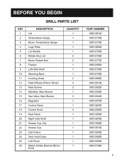
BEFORE YOU BEGIN GRILL PARTS LIST KEY 1 2 3 4 5 6 7 8 9 10 11 12 13 14 15 16 17 18 19 20 21 22 23 24 25 26 DESCRIPTION Lid Temperature Gauge Bezel, ...
BEFORE YOU BEGIN GRILL PARTS LIST KEY 1 2 3 4 5 6 7 8 9 10 11 12 13 14 15 16 17 18 19 20 21 22 23 24 25 26 DESCRIPTION Lid Temperature Gauge Bezel, ...

User Guide
Page 6
BEFORE YOU BEGIN GRILL PARTS LIST KEY 27 28 29 30 31 32 33 DESCRIPTION Match Holder Tank Baffle Right Panel Front Panel Bottom Shelf Standard Caster Foot QUANTITY 1 1 1 1 1 2 2 PART NUMBER 990137100 990139600 990135600 990130000 990129800 990128900 990129000 6
BEFORE YOU BEGIN GRILL PARTS LIST KEY 27 28 29 30 31 32 33 DESCRIPTION Match Holder Tank Baffle Right Panel Front Panel Bottom Shelf Standard Caster Foot QUANTITY 1 1 1 1 1 2 2 PART NUMBER 990137100 990139600 990135600 990130000 990129800 990128900 990129000 6

User Guide
Page 8
Remove all the parts out of protective styrofoam as shown in Fig. Open shipping box by slicing down its edges with a box cutter. A Styrofoam 8 STEP 1: 1. Take out all parts from plastic bags. A. ASSEMBLY BEFORE THE ASSEMBLY READ AND FOLLOW THE INSTRUCTIONS BELOW TO CORRECTLY UNPACK GRILL PARTS FROM SHIPPING BOX. Grill Head Left and Right Panels Grill Head Bottom Shelf Warming Rack Front Panel Tank Baffle Cart Frame Fig.
Remove all the parts out of protective styrofoam as shown in Fig. Open shipping box by slicing down its edges with a box cutter. A Styrofoam 8 STEP 1: 1. Take out all parts from plastic bags. A. ASSEMBLY BEFORE THE ASSEMBLY READ AND FOLLOW THE INSTRUCTIONS BELOW TO CORRECTLY UNPACK GRILL PARTS FROM SHIPPING BOX. Grill Head Left and Right Panels Grill Head Bottom Shelf Warming Rack Front Panel Tank Baffle Cart Frame Fig.

User Guide
Page 9
B below. B Hardware Pack 9 Styrofoam Heat Diffusers Grease Cup Clip and Grease Cup Positioning Gage Grill Head Cooking Grids Cardboard Box Left and Right Shelves Tank Hold Chain Feet Casters Fig. ASSEMBLY BEFORE THE ASSEMBLY STEP 2: 1. Open grill lid, and take out the small boxes packed within the grill head. Remove all packing materials and remove all parts from boxes as shown in Fig.
B below. B Hardware Pack 9 Styrofoam Heat Diffusers Grease Cup Clip and Grease Cup Positioning Gage Grill Head Cooking Grids Cardboard Box Left and Right Shelves Tank Hold Chain Feet Casters Fig. ASSEMBLY BEFORE THE ASSEMBLY STEP 2: 1. Open grill lid, and take out the small boxes packed within the grill head. Remove all packing materials and remove all parts from boxes as shown in Fig.

User Guide
Page 14
Note regulator hose is hanging outside of grill head. 2. Carefully lower the grill head onto the cart. Make sure the regulator hose is routed outside the cart. two (2) M6 x 26 screws in the back as shown in the front; ASSEMBLY ASSEMBLY STEPS STEP 4: Grill Head to cart with two (2) M6 x 13 screws and two (2) M6 flat washer in Fig. 4. Attach head to Cart 1. Fig. 4 14 Remove the tie wraps securing regulator hose to underside of cart.
Note regulator hose is hanging outside of grill head. 2. Carefully lower the grill head onto the cart. Make sure the regulator hose is routed outside the cart. two (2) M6 x 26 screws in the back as shown in the front; ASSEMBLY ASSEMBLY STEPS STEP 4: Grill Head to cart with two (2) M6 x 13 screws and two (2) M6 flat washer in Fig. 4. Attach head to Cart 1. Fig. 4 14 Remove the tie wraps securing regulator hose to underside of cart.

User Guide
Page 19
... appliance must be checked by a unique triangular hand wheel. POST-ASSEMBLY GAS CONNECTION ONLY USE THE REGULATOR AND HOSE ASSEMBLY PROVIDED WITH THIS GRILL. The installation of this type of valve (as the figure shown on the next page). 19 Provides a shut-off valve terminating in...LP tank may be acceptable for LP gas cylinders of Canada, CAN/CSA-B339, Cylinders, Spheres, and Tubes for marking. 4. This is identified by your grill provided they are compatible with the specification for use . Measurement: 12" (30.5-cm) diameter x 18" (45.7-cm) tall. 2. Only use a ...
... appliance must be checked by a unique triangular hand wheel. POST-ASSEMBLY GAS CONNECTION ONLY USE THE REGULATOR AND HOSE ASSEMBLY PROVIDED WITH THIS GRILL. The installation of this type of valve (as the figure shown on the next page). 19 Provides a shut-off valve terminating in...LP tank may be acceptable for LP gas cylinders of Canada, CAN/CSA-B339, Cylinders, Spheres, and Tubes for marking. 4. This is identified by your grill provided they are compatible with the specification for use . Measurement: 12" (30.5-cm) diameter x 18" (45.7-cm) tall. 2. Only use a ...
User Guide
Page 20
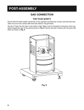
Secure the tank in place with the heat shield or the grill head. POST-ASSEMBLY GAS CONNECTION FOR YOUR SAFETY: Ensure that the hose does not come into the hole in Fig. 9. Fig. 9 20 Make sure the threaded connection at the top points toward the rear of the regulator provided are in place and that the black plastic grommets of the grill as shown in the bottom shelf. Set the LP tank into contact with the tank hold chain as shown in Fig. 9.
Secure the tank in place with the heat shield or the grill head. POST-ASSEMBLY GAS CONNECTION FOR YOUR SAFETY: Ensure that the hose does not come into the hole in Fig. 9. Fig. 9 20 Make sure the threaded connection at the top points toward the rear of the regulator provided are in place and that the black plastic grommets of the grill as shown in the bottom shelf. Set the LP tank into contact with the tank hold chain as shown in Fig. 9.
User Guide
Page 21
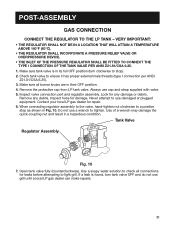
...position (turn tank valve OFF and do not use cap and strap supplied with valve. 5. Make sure all connections for any debris. Always use grill until a local LP gas dealer can make repairs. 21 Inspect hose for repair. 6. Tank Valve Regulator Assembly Fig. 10 7. When connecting ... result in their OFF position. 4. Use a soapy water solution to check all burner knobs are in a hazardous condition. Never attempt to light grill. Remove any damage or debris. Contact your local LP gas dealer for damage. Open tank valve fully (counterclockwise). Make sure tank valve is found...
...position (turn tank valve OFF and do not use cap and strap supplied with valve. 5. Make sure all connections for any debris. Always use grill until a local LP gas dealer can make repairs. 21 Inspect hose for repair. 6. Tank Valve Regulator Assembly Fig. 10 7. When connecting ... result in their OFF position. 4. Use a soapy water solution to check all burner knobs are in a hazardous condition. Never attempt to light grill. Remove any damage or debris. Contact your local LP gas dealer for damage. Open tank valve fully (counterclockwise). Make sure tank valve is found...

User Guide
Page 22
... these instructions exactly could start a fire causing death or serious injury. • NEVER store a spare LP tank under or near grill or in use this grill to stop a gas leak, close the LP tank valve IMMEDIATELY and call the fire department. Install the protective cap back onto the...on the spare LP tank, IMMEDIATELY step away from tank valve by turning the quick-coupling nut counterclockwise. 4. Detach the regulator assembly from the grill and call the LP gas supplier or the fire department. POST-ASSEMBLY GAS CONNECTION wWARNING • Never insert any gas leaks are detected. &#...
... these instructions exactly could start a fire causing death or serious injury. • NEVER store a spare LP tank under or near grill or in use this grill to stop a gas leak, close the LP tank valve IMMEDIATELY and call the fire department. Install the protective cap back onto the...on the spare LP tank, IMMEDIATELY step away from tank valve by turning the quick-coupling nut counterclockwise. 4. Detach the regulator assembly from the grill and call the LP gas supplier or the fire department. POST-ASSEMBLY GAS CONNECTION wWARNING • Never insert any gas leaks are detected. &#...

User Guide
Page 23
... to possible mishandling in shipment or excessive pressure unknowingly being applied to shipment, a complete gas tightness check must be used on the grill are in a well-ventilated area, away from ignition sources such as gas-fired or electrical appliances and flammable materials. 6. Substitution will... TESTING GENERAL • Although all connections have been checked and do not leak. 23 Do not smoke while leak-testing. 3. Keep grill away from the grill, including the burner tie-down straps. 2. Call your gas dealer or fire department. 4. If soap bubbles appear, there is full....
... to possible mishandling in shipment or excessive pressure unknowingly being applied to shipment, a complete gas tightness check must be used on the grill are in a well-ventilated area, away from ignition sources such as gas-fired or electrical appliances and flammable materials. 6. Substitution will... TESTING GENERAL • Although all connections have been checked and do not leak. 23 Do not smoke while leak-testing. 3. Keep grill away from the grill, including the burner tie-down straps. 2. Call your gas dealer or fire department. 4. If soap bubbles appear, there is full....
User Guide
Page 24
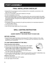
...8226; Knobs turn the knob slowly counterclockwise to the "OFF" position. 2. Turn gas supply off valve location. TO LIGHT MAIN BURNERS OF THE GRILL: Read instructions before use. Shutdown instructions: 1. Open the lid and make sure all control knobs to the ignite position ( ) as shown ... 11 4. POST-ASSEMBLY FINAL INSTALLATION CHECKLIST • At least 36" (91-cm) clearance must be maintained from combustible constructions to the grill are provided by the manufacturer. Swing the burner slightly after removal and cleaning. BEFORE LIGHTING: • Inspect the gas supply hose before ...
...8226; Knobs turn the knob slowly counterclockwise to the "OFF" position. 2. Turn gas supply off valve location. TO LIGHT MAIN BURNERS OF THE GRILL: Read instructions before use. Shutdown instructions: 1. Open the lid and make sure all control knobs to the ignite position ( ) as shown ... 11 4. POST-ASSEMBLY FINAL INSTALLATION CHECKLIST • At least 36" (91-cm) clearance must be maintained from combustible constructions to the grill are provided by the manufacturer. Swing the burner slightly after removal and cleaning. BEFORE LIGHTING: • Inspect the gas supply hose before ...
User Guide
Page 25
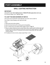
... open when lighting burners. Remove match holder from knot on the end of base. Tools: Match holder (hanging under right-side shelf) Usage: 1. POST-ASSEMBLY GRILL LIGHTING INSTRUCTION IMPORTANT: Lid must be match-lit.
... open when lighting burners. Remove match holder from knot on the end of base. Tools: Match holder (hanging under right-side shelf) Usage: 1. POST-ASSEMBLY GRILL LIGHTING INSTRUCTION IMPORTANT: Lid must be match-lit.
User Guide
Page 26
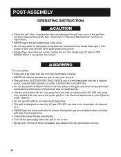
... grease fire occurs. Turn knobs and LP tank to extinguish the grease fire, because it . • NEVER light the burner with the lid closed grill may cause body injury. NEVER use in a enclosed area such as a carport, porch, covered patio, garage, or under wood balconies. • This... not been cleaned frequently. DO NOT use water to OFF IMMEDIATELY if any flammable material. • NEVER let children operate the grill or play near the grill. • This grill is not in case grease fire occurs. • Grease fires cannot be put out by closing the lid. wWARNING For your safety: ...
... grease fire occurs. Turn knobs and LP tank to extinguish the grease fire, because it . • NEVER light the burner with the lid closed grill may cause body injury. NEVER use in a enclosed area such as a carport, porch, covered patio, garage, or under wood balconies. • This... not been cleaned frequently. DO NOT use water to OFF IMMEDIATELY if any flammable material. • NEVER let children operate the grill or play near the grill. • This grill is not in case grease fire occurs. • Grease fires cannot be put out by closing the lid. wWARNING For your safety: ...
User Guide
Page 27
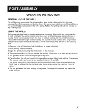
... after the initial browning. The longer the preheat, the faster the meat browns. 27 POST-ASSEMBLY OPERATING INSTRUCTION GENERAL USE OF THE GRILL: The grill burners encompass the entire cooking area and are stainless-steel heat diffusers. Above the burners are side-ported to any position between HI ...-steel flame tamers under the cast iron cooking grids. 8. Light the grill burners using the instructions in the juices. The hot grill sears the food, sealing in this manual. 4. Heat is designed to HI and preheat the grill for a long time or basted with a sugary marinade may need a...
... after the initial browning. The longer the preheat, the faster the meat browns. 27 POST-ASSEMBLY OPERATING INSTRUCTION GENERAL USE OF THE GRILL: The grill burners encompass the entire cooking area and are stainless-steel heat diffusers. Above the burners are side-ported to any position between HI ...-steel flame tamers under the cast iron cooking grids. 8. Light the grill burners using the instructions in the juices. The hot grill sears the food, sealing in this manual. 4. Heat is designed to HI and preheat the grill for a long time or basted with a sugary marinade may need a...
User Guide
Page 28
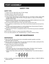
...is not in the HI position, as following: • Remove cooking grids and flame tamers. • Light burners. • Turn knobs from the grill. 8. Bubbles indicate leaks. 5. LP tanks must have threaded valve plugs tightly installed and must be smaller than in use . Never leave an LP tank... POST-ASSEMBLY SAFETY TIPS SAFETY TIPS: 1. Disconnected LP tanks in or near the shut-off all control knobs and LP tank valve when the grill is handy to LO and check the flame status. Check all of the cart clear and free from combustible materials, gasoline, and other problems...
...is not in the HI position, as following: • Remove cooking grids and flame tamers. • Light burners. • Turn knobs from the grill. 8. Bubbles indicate leaks. 5. LP tanks must have threaded valve plugs tightly installed and must be smaller than in use . Never leave an LP tank... POST-ASSEMBLY SAFETY TIPS SAFETY TIPS: 1. Disconnected LP tanks in or near the shut-off all control knobs and LP tank valve when the grill is handy to LO and check the flame status. Check all of the cart clear and free from combustible materials, gasoline, and other problems...
User Guide
Page 29
...any food particles. This is completed. Yellow flame with a metal scraper. Burners make popping noises. 29 Steam, created as water contacts the hot grill, assists the cleaning process by softening any clogged ports with a wire brush. WHEN TO LOOK FOR SPIDERS Inspect the burners at least once a... storing. VERY IMPORTANT: The orifice of the grease tray to absorb the grease. The food particles will not rise. 3. Make sure the grill is cool. • Clean the exterior of the following conditions occur: 1. SPIDER AND INSECT WARNING Spiders and insects can cause fires inside ...
...any food particles. This is completed. Yellow flame with a metal scraper. Burners make popping noises. 29 Steam, created as water contacts the hot grill, assists the cleaning process by softening any clogged ports with a wire brush. WHEN TO LOOK FOR SPIDERS Inspect the burners at least once a... storing. VERY IMPORTANT: The orifice of the grease tray to absorb the grease. The food particles will not rise. 3. Make sure the grill is cool. • Clean the exterior of the following conditions occur: 1. SPIDER AND INSECT WARNING Spiders and insects can cause fires inside ...