Operation Manual
Page 1
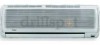
SPLIT TYPE ROOM AIR CONDITIONER OPERATION MANUAL HSUO9XC7 HSU12XC7 • Please read this operation manual before using the air conditioner. No. 0010557227
SPLIT TYPE ROOM AIR CONDITIONER OPERATION MANUAL HSUO9XC7 HSU12XC7 • Please read this operation manual before using the air conditioner. No. 0010557227

Operation Manual
Page 2
... Operation Maintenance Troubleshooting Warning 2 3-5 6-12 13-14 15 1.The power connection for test running in normal operation. is reached at the main power distribution.This distribution has to be connected to this power line. 3.For unit power ratings ,please refer to adjust up and down air flow. (Do not adjust it manually.) Power indicator Lights up during compressor operation. 1 Emergency switch(manual) Used when remote controller is received. Parts and Functionui Inlet grille Air filter...
... Operation Maintenance Troubleshooting Warning 2 3-5 6-12 13-14 15 1.The power connection for test running in normal operation. is reached at the main power distribution.This distribution has to be connected to this power line. 3.For unit power ratings ,please refer to adjust up and down air flow. (Do not adjust it manually.) Power indicator Lights up during compressor operation. 1 Emergency switch(manual) Used when remote controller is received. Parts and Functionui Inlet grille Air filter...

Operation Manual
Page 3
... wire. 6. The connecting wire,power supply wire and power plug are included with local wiring standards. 2. Damaged power supply cords shoule be a minimum of 6 feet(2 meters). 12. The wiring diagram is broken replace with type T3.15A/250V. 9. Use 25A/250V power plug. 7. Parts and Functions Outdoor Unit CONNECTING REFRIGERANT PIPING AND ELECTRICAL WIRING AIR INLET AIR OUTLET , DRAIN HOSE Notes: 1. If the fuse on adequate support. 13. Use 25A breaker.The distance between the indoor unit and the floor should be installed in a location...
... wire. 6. The connecting wire,power supply wire and power plug are included with local wiring standards. 2. Damaged power supply cords shoule be a minimum of 6 feet(2 meters). 12. The wiring diagram is broken replace with type T3.15A/250V. 9. Use 25A/250V power plug. 7. Parts and Functions Outdoor Unit CONNECTING REFRIGERANT PIPING AND ELECTRICAL WIRING AIR INLET AIR OUTLET , DRAIN HOSE Notes: 1. If the fuse on adequate support. 13. Use 25A breaker.The distance between the indoor unit and the floor should be installed in a location...
Operation Manual
Page 4
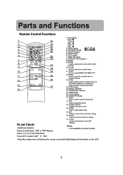
... button, "AM" or "PM" flashes. Press A or p to select TIMER ON,TIMER OFF 13. FAN SPEED display AUTO LO MED HI =SI = = = 4. TIMER Used to set correct time. 1. CODE Used to select desired temperature. 22. POWER/SOFT display* 18. display 19. TEMP Used to select code A or B with a press,A or B will briefly display all information on some models. SWING display 3. LOCK display 7. TIMER ON display 8. AUXILIARY HEAT display * 9. CLOCK Used to set Clock: Install new batteries. POWER ON/OFF Used for unit start or stop 24. Mode display AUTO 0 COOL DRY...
... button, "AM" or "PM" flashes. Press A or p to select TIMER ON,TIMER OFF 13. FAN SPEED display AUTO LO MED HI =SI = = = 4. TIMER Used to set correct time. 1. CODE Used to select desired temperature. 22. POWER/SOFT display* 18. display 19. TEMP Used to select code A or B with a press,A or B will briefly display all information on some models. SWING display 3. LOCK display 7. TIMER ON display 8. AUXILIARY HEAT display * 9. CLOCK Used to set Clock: Install new batteries. POWER ON/OFF Used for unit start or stop 24. Mode display AUTO 0 COOL DRY...
Operation Manual
Page 5
... be used for a long period of the remote control. AM ettl, c) 0 TEMP ON OFF MODE 0 SLEEP 0 CLOCK 0 0 TI , :1)ER 0 SET CD RESET CODE • • LOCK -7- , V 6 Installing Batteries Slightly press "v " and push down to be reduced if there is in use a sharp pointed instrument to press the reset key located on the indoor unit. • The distance between the remote control and the receiver hole should be removed from...
... be used for a long period of the remote control. AM ettl, c) 0 TEMP ON OFF MODE 0 SLEEP 0 CLOCK 0 0 TI , :1)ER 0 SET CD RESET CODE • • LOCK -7- , V 6 Installing Batteries Slightly press "v " and push down to be reduced if there is in use a sharp pointed instrument to press the reset key located on the indoor unit. • The distance between the remote control and the receiver hole should be removed from...
Operation Manual
Page 6
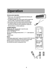
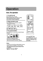
TEMP (0 SWING 4 MODE SLEEP CD CLOCK SET CTDIMEECRDDIED RESET CODE • • LOCK O (4) To stop the unit Press ON/OFF button. Only time is not available in FAN mode. Notes: The Remote control will not appear on display) Power indicator on indoor unit lights up. (2) Select operation mode Press MODE button. Unit stops. Operation Auto, Fan operation (1) To start the unit Press ON/OFF button.Unit starts. Note:AUTO is displayed on display. (Timer setting will keep MODE settings in selected mode. Vertical flap on cool-only models. For each press, fan speed ...
TEMP (0 SWING 4 MODE SLEEP CD CLOCK SET CTDIMEECRDDIED RESET CODE • • LOCK O (4) To stop the unit Press ON/OFF button. Only time is not available in FAN mode. Notes: The Remote control will not appear on display) Power indicator on indoor unit lights up. (2) Select operation mode Press MODE button. Unit stops. Operation Auto, Fan operation (1) To start the unit Press ON/OFF button.Unit starts. Note:AUTO is displayed on display. (Timer setting will keep MODE settings in selected mode. Vertical flap on cool-only models. For each press, fan speed ...
Operation Manual
Page 7
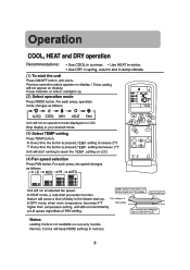
... the TEMP . A Every time the button is pressed,TEMP.setting increases 2°F V Every time the button is not available on indoor unit lights up . ' COOL operation starts when room temp. Remote Control will not appear on display) Power indicator on cool-only models. Unit starts. Previous operation status appears on LCD. (4) Fan speed selection LO MEDH-I AU-TO Press FAN button. button. is higher than TEMP setting. .1 V TEMP setting+4°F Ultra-low air flow In DRY mode, when room temperature becomes 4°F TEMP setting higher than temperature setting, unit will...
... the TEMP . A Every time the button is pressed,TEMP.setting increases 2°F V Every time the button is not available on indoor unit lights up . ' COOL operation starts when room temp. Remote Control will not appear on display) Power indicator on cool-only models. Unit starts. Previous operation status appears on LCD. (4) Fan speed selection LO MEDH-I AU-TO Press FAN button. button. is higher than TEMP setting. .1 V TEMP setting+4°F Ultra-low air flow In DRY mode, when room temperature becomes 4°F TEMP setting higher than temperature setting, unit will...
Operation Manual
Page 8
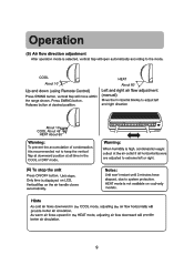
... or right. (6) To stop the unit Press ON/OFF button. Unit stops. LOperation (5) Air flow direction adjustment After operation mode is displayed on LCD. Vertical flap on cool-only models. \.. .1 Hints As cold air flows downward in the HEAT mode, adjusting air flow downward will open automatically according to the mode. HEAT mode is recommended not to extreme left and right direction r About 10° COOL About 45° HEAT About 60° r Warning...
... or right. (6) To stop the unit Press ON/OFF button. Unit stops. LOperation (5) Air flow direction adjustment After operation mode is displayed on LCD. Vertical flap on cool-only models. \.. .1 Hints As cold air flows downward in the HEAT mode, adjusting air flow downward will open automatically according to the mode. HEAT mode is recommended not to extreme left and right direction r About 10° COOL About 45° HEAT About 60° r Warning...
Operation Manual
Page 9
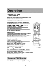
... TEMP CD SWING 1 FAN r MODE SLEEP SET TIMER V 6 2 45 RESET CODE . . (6) Time confirming for TIMER OFF After time setting, press SET button to change quickly. A Every time the button is pressed, time decreases 10 minutes. Time can be shown on LCD. If button is pressed, display changes as follows: 0 I. Power indicator on LCD. ON -. blank TIMER ON TIMER OFF TIMER ON-OFF Select TIMER ON-OFF "ON" will be displayed on indoor unit lights up. (2) Press TIMER button...
... TEMP CD SWING 1 FAN r MODE SLEEP SET TIMER V 6 2 45 RESET CODE . . (6) Time confirming for TIMER OFF After time setting, press SET button to change quickly. A Every time the button is pressed, time decreases 10 minutes. Time can be shown on LCD. If button is pressed, display changes as follows: 0 I. Power indicator on LCD. ON -. blank TIMER ON TIMER OFF TIMER ON-OFF Select TIMER ON-OFF "ON" will be displayed on indoor unit lights up. (2) Press TIMER button...

Operation Manual
Page 10
...°F. not for use during normal operation. • Continue to change the temperature settings, air flow speed, or use the timer feature. 1 For test operation: • To test operation ,use when the room temperature is not possible to press the test operation switch for more than 5 seconds. Cooling operation will start of the operation. I 11 Operation Emergency operation and test operation Emergency Operation Switch: • Follow these instructions only when the remote control is defective or lost...
...°F. not for use during normal operation. • Continue to change the temperature settings, air flow speed, or use the timer feature. 1 For test operation: • To test operation ,use when the room temperature is not possible to press the test operation switch for more than 5 seconds. Cooling operation will start of the operation. I 11 Operation Emergency operation and test operation Emergency Operation Switch: • Follow these instructions only when the remote control is defective or lost...

Operation Manual
Page 11
...: SLEEP operation starts 1 hr SLEEP operation stops Approx. 6 hrs Rises 2°F 1 hr Rises 2°F Temp. setting Unit stop • The SLEEP feature is not available in the FAN mode. • In the event of a power interruption, a time delay feature will run at 6 degrees below the set temperature. 6 th through 8 th hour-the unit will run at 2 degrees above the set temperature. 3 rd through 8 th hour-the unit will prevent the compressor...
...: SLEEP operation starts 1 hr SLEEP operation stops Approx. 6 hrs Rises 2°F 1 hr Rises 2°F Temp. setting Unit stop • The SLEEP feature is not available in the FAN mode. • In the event of a power interruption, a time delay feature will run at 6 degrees below the set temperature. 6 th through 8 th hour-the unit will run at 2 degrees above the set temperature. 3 rd through 8 th hour-the unit will prevent the compressor...
Operation Manual
Page 12
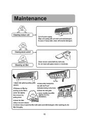
..."Front" 2.Release air filter by indication facing to remove dust,or wash the filter with dry cloth only. am 000 00 using a vacuum cleaner to the front. Cleaning remote controll ° • ) - ------> Clean remote control with water and mild detergent. Maintenance CCleaning indoor unit -). _J Cut off power supply, Wipe unit casing with glass cleaner or chemicals. } ../ r \ t ir• I 1.Open inlet grille by pulling grille upward. Cleaning air filter Do not clean with soft cloth...
..."Front" 2.Release air filter by indication facing to remove dust,or wash the filter with dry cloth only. am 000 00 using a vacuum cleaner to the front. Cleaning remote controll ° • ) - ------> Clean remote control with water and mild detergent. Maintenance CCleaning indoor unit -). _J Cut off power supply, Wipe unit casing with glass cleaner or chemicals. } ../ r \ t ir• I 1.Open inlet grille by pulling grille upward. Cleaning air filter Do not clean with soft cloth...

Operation Manual
Page 13
Do not block the inlet or outlet. 00 , r / p-,,..,,/i-l,i.,--p Do not pull power plug. . . 0 *te E ;) Do not use for other purposes woo Such as refrigeration. 14 Maintenance Use & care r Avoid contact with water.
Do not block the inlet or outlet. 00 , r / p-,,..,,/i-l,i.,--p Do not pull power plug. . . 0 *te E ;) Do not use for other purposes woo Such as refrigeration. 14 Maintenance Use & care r Avoid contact with water.

Operation Manual
Page 14
... COOL or DRY operation, indoor unit _,, _ may be heard. This is interrupted, a time delay of temperature changes. •Air filter may blow out mist. This noise is heard Normal Performance inspection ,--., II I , Poor cooling i 0a C i /ri"---- - • o• !6 () • Is power plug inserted? • Is there a power failure? • Is fuse blown out? • Is the air filter dirty? Noise is generated by refrigerant flowing in the room during the cooling operation?(Close...
... COOL or DRY operation, indoor unit _,, _ may be heard. This is interrupted, a time delay of temperature changes. •Air filter may blow out mist. This noise is heard Normal Performance inspection ,--., II I , Poor cooling i 0a C i /ri"---- - • o• !6 () • Is power plug inserted? • Is there a power failure? • Is fuse blown out? • Is the air filter dirty? Noise is generated by refrigerant flowing in the room during the cooling operation?(Close...


