User Manual
Page 1
INSTALLATION MANUAL ROOM AIR CONDITIONER WALL MOUNTED TYPE HSM 09HEK03/R2(DB) HSM 12HEK03/R2(DB) HUM 09HA03/R2(DB) HUM 12HA03/R2(DB) Read this manual before installation Explain sufficiently the operating means to the user according to this manual. NO.001051
INSTALLATION MANUAL ROOM AIR CONDITIONER WALL MOUNTED TYPE HSM 09HEK03/R2(DB) HSM 12HEK03/R2(DB) HUM 09HA03/R2(DB) HUM 12HA03/R2(DB) Read this manual before installation Explain sufficiently the operating means to the user according to this manual. NO.001051
User Manual
Page 2
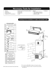
... for indoor and outdoor E Drain hose F Heating insulating material G Piping hole cover more than 10cm Arrangement of indoor and outdoor units Accessory parts No. more than 10cm D more than 60cm Note:Cooling only units don't have Drain-elbow The marks from A to the rising up of drain hose more than 10cm more than 10cm more than 2m. Accessory parts Number of articles 1 Remote controller 1 more than 5cm 2 R-03 dry battery 2 3 1 Mounting plate 4 1 Drain hose 5 4X50...
... for indoor and outdoor E Drain hose F Heating insulating material G Piping hole cover more than 10cm Arrangement of indoor and outdoor units Accessory parts No. more than 10cm D more than 60cm Note:Cooling only units don't have Drain-elbow The marks from A to the rising up of drain hose more than 10cm more than 10cm more than 2m. Accessory parts Number of articles 1 Remote controller 1 more than 5cm 2 R-03 dry battery 2 3 1 Mounting plate 4 1 Drain hose 5 4X50...
User Manual
Page 3
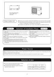
Place, possible to drain easily, where piping can be left. Place, where cold air can be supported sufficiently. Place, nearby a power receptacle, with the outdoor unit. In the case of fixing the remote controller on a wall, place where the indoor unit can be connected with enough space around. (Refer to drawings). For 09 Liquid pipe ( ) 6.35mm(1/4") Gas pipe ( ) 9.52mm(3/8") For 12 6.35mm(1/4") 9.52mm(3/8") 2 Place, not affected...
Place, possible to drain easily, where piping can be left. Place, where cold air can be supported sufficiently. Place, nearby a power receptacle, with the outdoor unit. In the case of fixing the remote controller on a wall, place where the indoor unit can be connected with enough space around. (Refer to drawings). For 09 Liquid pipe ( ) 6.35mm(1/4") Gas pipe ( ) 9.52mm(3/8") For 12 6.35mm(1/4") 9.52mm(3/8") 2 Place, not affected...
User Manual
Page 4
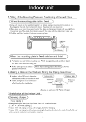
... the wall hole location A using a measuring tape B= 60mm 30mm A=145mm When the mounting plate is fixed side bar and lintel Fix to side bar and lintel a mounting bar, Which is marked on heat insulation materials. 3 Install piping hole cover and seal it off with putty after installation Indoor side Wall hole 60mm Outdoor side Thickness of wall (Section of wall hole) G Piping hole pipe 3.Installation of the Indoor Unit Drawing of pipe [ Rear piping ] Draw pipes and the drain hose...
... the wall hole location A using a measuring tape B= 60mm 30mm A=145mm When the mounting plate is fixed side bar and lintel Fix to side bar and lintel a mounting bar, Which is marked on heat insulation materials. 3 Install piping hole cover and seal it off with putty after installation Indoor side Wall hole 60mm Outdoor side Thickness of wall (Section of wall hole) G Piping hole pipe 3.Installation of the Indoor Unit Drawing of pipe [ Rear piping ] Draw pipes and the drain hose...
User Manual
Page 5
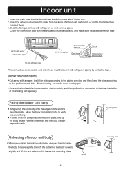
... the body from side to side to leave agraffe,then lift the bottom of wall hole. Indoor unit 1. Insert the drain hose into the dent of heat insulation materials of the mounting plate. mounting plate Unloading of indoor unit, and pull it down perpendicularly. agraffe 4 mounting plate Insert the indoor/outdoor electric cable from the underside and then put it out on the front side...
... the body from side to side to leave agraffe,then lift the bottom of wall hole. Indoor unit 1. Insert the drain hose into the dent of heat insulation materials of the mounting plate. mounting plate Unloading of indoor unit, and pull it down perpendicularly. agraffe 4 mounting plate Insert the indoor/outdoor electric cable from the underside and then put it out on the front side...
User Manual
Page 6
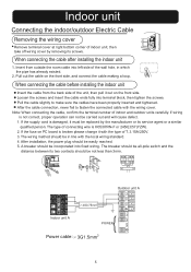
... installation, the power plug should be all-pole switch and the distance between its screws. The breaker should be incorporated into fixed wiring. If wiring is H05/07RN-F or 245IEC57(YZW). 2. Indoor unit Connecting the indoor/outdoor Electric Cable Removing the wiring cover Remove terminal cover at right bottom corner of indoor unit, then take off wiring cover by the manufacturer or its service agent or a similar qualified person. If the supply cord...
... installation, the power plug should be all-pole switch and the distance between its screws. The breaker should be incorporated into fixed wiring. If wiring is H05/07RN-F or 245IEC57(YZW). 2. Indoor unit Connecting the indoor/outdoor Electric Cable Removing the wiring cover Remove terminal cover at right bottom corner of indoor unit, then take off wiring cover by the manufacturer or its service agent or a similar qualified person. If the supply cord...
User Manual
Page 7
... the plugs fully into terminal block, then tighten the screws. The max vertical distance between the indoor unit and the outdoor unit is used, please attach it as figure. (Note: Only for the installation of indoor and outdoor units 2.Connection of pipes To bend a pipe, give the roundness as large as possible not to terminal number in the same manner as the indoor unit. Half...
... the plugs fully into terminal block, then tighten the screws. The max vertical distance between the indoor unit and the outdoor unit is used, please attach it as figure. (Note: Only for the installation of indoor and outdoor units 2.Connection of pipes To bend a pipe, give the roundness as large as possible not to terminal number in the same manner as the indoor unit. Half...
User Manual
Page 8
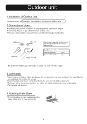
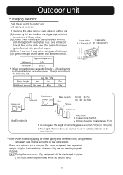
... following list. Brand new outdoor unit is less than regulated weight. Note: When extending piping, air inside piping shall be used to 3-way valve. (3) Loosen 2-way valve by 90o using specified torque. (5) Tighten the caps on the valves with specified torque. Outdoor unit 5.Purging Method: Push the air out of the indoor unit and piping as followes: (1) Remove the valve cap on 2-way valve in outdoor unit. (2) Loosen by 1/2 turn...
... following list. Brand new outdoor unit is less than regulated weight. Note: When extending piping, air inside piping shall be used to 3-way valve. (3) Loosen 2-way valve by 90o using specified torque. (5) Tighten the caps on the valves with specified torque. Outdoor unit 5.Purging Method: Push the air out of the indoor unit and piping as followes: (1) Remove the valve cap on 2-way valve in outdoor unit. (2) Loosen by 1/2 turn...
User Manual
Page 9
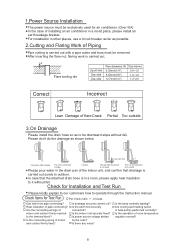
... be exclusively used for air conditioner. (Over I0A) In the case of indoor and outdoor firmly inserted to operate through the instruction manual. Are cooling and heating (when in boxes Gas leak from a ditch Please pour water in the drain pan of Piping Pipe cutting is carried out. In case that drainage is in other places, use a circuit breaker as far as possible. 2.Cutting and Flaring Work of the indoor unit, and...
... be exclusively used for air conditioner. (Over I0A) In the case of indoor and outdoor firmly inserted to operate through the instruction manual. Are cooling and heating (when in boxes Gas leak from a ditch Please pour water in the drain pan of Piping Pipe cutting is carried out. In case that drainage is in other places, use a circuit breaker as far as possible. 2.Cutting and Flaring Work of the indoor unit, and...


