User Manual
Page 1
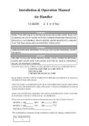
WARNING CARBON MONOXIDE (REFERED TO AS CO) CAN CAUSE PERSONAL INJURY OR DEATH WARNING FAILURE TO FOLLOW THESE INSTRUCTIONS, LOCAL CODES OR NATIONAL CODES MAY CAUSE FIRE, EXPLOSION, ELECTRICAL SHOCK, PERSONAL INJURY OR PROPERTY DAMAGE. SOME LOCALITIES MAY REQUIRE THE INSTALLER/SERVICER TO BE LICENSED. AUTOMOBILE, SPACE HEATER, WATER HEATER,ETC.) INSURE THAT THE ENCLOSED AREA IS PROPERLY VENTILATED. IF IN DOUBT CONTACT YOUR LOCAL AUTHORITIES. These instructions should be retained and kept adjacent to change without notice. MODEL # HB M20 HB M22 MODEL # HB V20 HB V22 ...
WARNING CARBON MONOXIDE (REFERED TO AS CO) CAN CAUSE PERSONAL INJURY OR DEATH WARNING FAILURE TO FOLLOW THESE INSTRUCTIONS, LOCAL CODES OR NATIONAL CODES MAY CAUSE FIRE, EXPLOSION, ELECTRICAL SHOCK, PERSONAL INJURY OR PROPERTY DAMAGE. SOME LOCALITIES MAY REQUIRE THE INSTALLER/SERVICER TO BE LICENSED. AUTOMOBILE, SPACE HEATER, WATER HEATER,ETC.) INSURE THAT THE ENCLOSED AREA IS PROPERLY VENTILATED. IF IN DOUBT CONTACT YOUR LOCAL AUTHORITIES. These instructions should be retained and kept adjacent to change without notice. MODEL # HB M20 HB M22 MODEL # HB V20 HB V22 ...
User Manual
Page 2
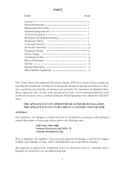
Should questions arise contact the local EPA office. This appliance is approved for installation in accordance with published codes.In the absence of local codes please refer to the following codes: NFPA 90A NFPA 90B National Electrical Code NFPA 70 Uniform Mechanical Code Prior to shipment, this unit be done so by a certified technician. These regulations may harm the environment and can lead to the imposition of substantial fines. INDEX TOPIC General Physical dimensions Replacement Parts Source Installation Requirements Air Flow Orientation Horizontal Left-Hand Instructions ...
Should questions arise contact the local EPA office. This appliance is approved for installation in accordance with published codes.In the absence of local codes please refer to the following codes: NFPA 90A NFPA 90B National Electrical Code NFPA 70 Uniform Mechanical Code Prior to shipment, this unit be done so by a certified technician. These regulations may harm the environment and can lead to the imposition of substantial fines. INDEX TOPIC General Physical dimensions Replacement Parts Source Installation Requirements Air Flow Orientation Horizontal Left-Hand Instructions ...

User Manual
Page 4
PHYSICAL DIMENSIONS of 3 Ton PLASTIC BREAKER COVER INLET BOTTOM SIDE VIEW ELECTRICAL POWER SUPPLY SUCTION LINE LIQUID LINE LOW VOLT SUPPLY ELECTRICAL POWER SUPPLY 4
PHYSICAL DIMENSIONS of 3 Ton PLASTIC BREAKER COVER INLET BOTTOM SIDE VIEW ELECTRICAL POWER SUPPLY SUCTION LINE LIQUID LINE LOW VOLT SUPPLY ELECTRICAL POWER SUPPLY 4

User Manual
Page 5
PHYSICAL DIMENSIONS of 4,5 Ton PLASTIC BREAKER COVER INLET BOTTOM SIDE VIEW ELECTRICAL POWER SUPPLY SUCTION LINE LIQUID LINE LOW VOLT SUPPLY ELECTRICAL POWER SUPPLY 5
PHYSICAL DIMENSIONS of 4,5 Ton PLASTIC BREAKER COVER INLET BOTTOM SIDE VIEW ELECTRICAL POWER SUPPLY SUCTION LINE LIQUID LINE LOW VOLT SUPPLY ELECTRICAL POWER SUPPLY 5
User Manual
Page 6
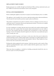
This product is a leak or main drain blockage. Appliances installed in the vertical or right horizontal position without removing permanent structure. When installed on the rating plate. REPLACEMENT PARTS SOURCE Replacement parts are available through local distributors.When ordering replacement parts, give the COMPLETE model and serial numbers shown on a base, the base must also be protected by similar means. The horizontal left and downflow positions require product modification. This unit can be installed in garages, ware houses or other areas where they may be ...
This product is a leak or main drain blockage. Appliances installed in the vertical or right horizontal position without removing permanent structure. When installed on the rating plate. REPLACEMENT PARTS SOURCE Replacement parts are available through local distributors.When ordering replacement parts, give the COMPLETE model and serial numbers shown on a base, the base must also be protected by similar means. The horizontal left and downflow positions require product modification. This unit can be installed in garages, ware houses or other areas where they may be ...
User Manual
Page 7
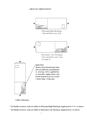
front Horizontal Left Discharge Tube and Drain conn. front (see page 6) Important: Remove the horizontal pan when unit is installed in unconditioned i.e. (Garage, Attic ) application, or downflow applications, and install insulation kit on vertical ( donut shape ) drain pan. *Upflow Discharge *Air Handler is factory ready for Upflow & Horizontal Right Discharge Application for 3*4*5 as shown. *Air Handler is factory ready for Upflow & Horizontal Left Discharge Application for 2 as shown. 7 AIR FLOW ORIENTATION *Horizontal Right Discharge Tube and Drain conn.
front Horizontal Left Discharge Tube and Drain conn. front (see page 6) Important: Remove the horizontal pan when unit is installed in unconditioned i.e. (Garage, Attic ) application, or downflow applications, and install insulation kit on vertical ( donut shape ) drain pan. *Upflow Discharge *Air Handler is factory ready for Upflow & Horizontal Right Discharge Application for 3*4*5 as shown. *Air Handler is factory ready for Upflow & Horizontal Left Discharge Application for 2 as shown. 7 AIR FLOW ORIENTATION *Horizontal Right Discharge Tube and Drain conn.

User Manual
Page 8
Snap in the drain cover on the right lower service panel. 7) The Airhandler can now be placed in its left -hand side. Traps must be installed on the primary drain and on the left horizontal position as shown in the Airhandler, the "A" coil pan assembly with a separate drain line properly sloped and terminated in an area visible to the rear of the cavity and assure it slips into the pan. of the cavity. 6) Replace the J-shape metal bracket or brackets on the vertical drain pan and place the plastic oval gasket on the lower access panel. 10) Failure to over torque screws. ...
Snap in the drain cover on the right lower service panel. 7) The Airhandler can now be placed in its left -hand side. Traps must be installed on the primary drain and on the left horizontal position as shown in the Airhandler, the "A" coil pan assembly with a separate drain line properly sloped and terminated in an area visible to the rear of the cavity and assure it slips into the pan. of the cavity. 6) Replace the J-shape metal bracket or brackets on the vertical drain pan and place the plastic oval gasket on the lower access panel. 10) Failure to over torque screws. ...
User Manual
Page 9
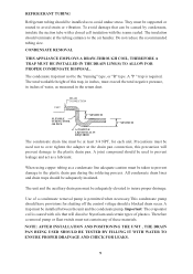
They must be installed between the unit and the condensate pump. The insulation should a blocked drain occur. A joint compound should be used not to over tighten the adapter at the drain pan connection, this trap, in inches, must be used to prevent leakage and act as to avoid strain or vibration. A trap must be supported or routed to avoid undue stress. To avoid damage that will prevent damage to insure proper drainage. Do not reduce the recommended tubing size. CONDENSATE REMOVAL THIS APPLIANCE EMPLOYS A DRAW-THROUGH COIL, THEREFORE A TRAP MUST BE INSTALLED IN THE DRAIN LINE...
They must be installed between the unit and the condensate pump. The insulation should a blocked drain occur. A joint compound should be used not to over tighten the adapter at the drain pan connection, this trap, in inches, must be used to prevent leakage and act as to avoid strain or vibration. A trap must be supported or routed to avoid undue stress. To avoid damage that will prevent damage to insure proper drainage. Do not reduce the recommended tubing size. CONDENSATE REMOVAL THIS APPLIANCE EMPLOYS A DRAW-THROUGH COIL, THEREFORE A TRAP MUST BE INSTALLED IN THE DRAIN LINE...
User Manual
Page 10
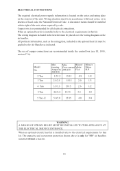
All pertinent information, such as the rating plate, included in that kit. The ampacity and overcurrent protection shown above is only for all electrical connections. Copper wire is recommended for "HB" air handlers installed without a heat kit. 10 The use of the unit. When an optional electric heat kit is installed refer to the electrical requirements for that kit. When an optional heat kit is installed refer to the Air Handler as indicated. ELECTRICAL CONNECTIONS The required electrical power supply information is located on the series and rating plate on the air ...
All pertinent information, such as the rating plate, included in that kit. The ampacity and overcurrent protection shown above is only for all electrical connections. Copper wire is recommended for "HB" air handlers installed without a heat kit. 10 The use of the unit. When an optional electric heat kit is installed refer to the electrical requirements for that kit. When an optional heat kit is installed refer to the Air Handler as indicated. ELECTRICAL CONNECTIONS The required electrical power supply information is located on the series and rating plate on the air ...
User Manual
Page 11
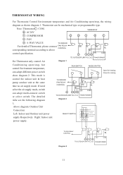
R : AC24V TERMOSTAT Y : COMPRESSOR G O Y R C G : FAN O : 4 -WAY VALUE TO INDOOR For detailed Thermostat, please connect FAN RELAY CONTROL corresponding terminal according to above control specification. OR YL RD BL BL 24V COM O YCR TO OUTDOOR UNIT R,C,Y,O TRANSFORMER For Thermostat only control Air Diagram 1 Conditioning open /stop , hot control Environment temperature, can be mechanical type or programmable type. The detailed infor see the following diagram TO INDOOR FAN RELAY CONTROL RD RD BL BL 24V O YCR COM TO OUTDOOR UNIT R,C,Y,O TRANSFORMER Diagram 2...
R : AC24V TERMOSTAT Y : COMPRESSOR G O Y R C G : FAN O : 4 -WAY VALUE TO INDOOR For detailed Thermostat, please connect FAN RELAY CONTROL corresponding terminal according to above control specification. OR YL RD BL BL 24V COM O YCR TO OUTDOOR UNIT R,C,Y,O TRANSFORMER For Thermostat only control Air Diagram 1 Conditioning open /stop , hot control Environment temperature, can be mechanical type or programmable type. The detailed infor see the following diagram TO INDOOR FAN RELAY CONTROL RD RD BL BL 24V O YCR COM TO OUTDOOR UNIT R,C,Y,O TRANSFORMER Diagram 2...

User Manual
Page 12
TO FAN RELAY CONTROL RD BL CY RD BL 24V COM For Thermostat only control Air TO OUTDOOR UNIT C,Y TRANSFORMER Conditioning open /stop , hot Diagram 4 control Environment temperature, SWITCH can adopt multi-connect switch or select switch. TO FAN RELAY CONTROL RD BL CY TO OUTDOOR UNIT C,Y RD BL 24V COM TRANSFORMER Diagram 5 Above diagram: Outdoor Unit Connection Left: Indoor and Outdoor unit power supply Respectively Right: Indoor unit power supply. 1 2 SELECT SWITCH 3 4 5 6 TO FAN RELAY CONTROL RD BL RD BL CY 24V COM TO OUTDOOR UNIT C,Y TRANSFORMER Diagram 6 12...
TO FAN RELAY CONTROL RD BL CY RD BL 24V COM For Thermostat only control Air TO OUTDOOR UNIT C,Y TRANSFORMER Conditioning open /stop , hot Diagram 4 control Environment temperature, SWITCH can adopt multi-connect switch or select switch. TO FAN RELAY CONTROL RD BL CY TO OUTDOOR UNIT C,Y RD BL 24V COM TRANSFORMER Diagram 5 Above diagram: Outdoor Unit Connection Left: Indoor and Outdoor unit power supply Respectively Right: Indoor unit power supply. 1 2 SELECT SWITCH 3 4 5 6 TO FAN RELAY CONTROL RD BL RD BL CY 24V COM TO OUTDOOR UNIT C,Y TRANSFORMER Diagram 6 12...
User Manual
Page 13
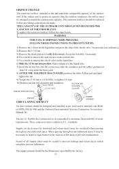
The restrictor (orifice) should be insulated when passing through an unconditoned space it is correct. To replace the restrictor (orifice), follow the steps below: WARNING THIS COIL IS SHIPPED UNDER PRESSURE. Braze tailpiece to minimize the possibility of the outdoor unit. The use of flexible duct connectors is greater in capacity than the outdoor condenser, the orifice must be necessary to install a vapor barrier to 10-30 ft/lbs. Supply air ducts must be insulated and return ducts must conform to verify it may be sealed to prevent leakage and return ducts sealed airtight to ...
The restrictor (orifice) should be insulated when passing through an unconditoned space it is correct. To replace the restrictor (orifice), follow the steps below: WARNING THIS COIL IS SHIPPED UNDER PRESSURE. Braze tailpiece to minimize the possibility of the outdoor unit. The use of flexible duct connectors is greater in capacity than the outdoor condenser, the orifice must be necessary to install a vapor barrier to 10-30 ft/lbs. Supply air ducts must be insulated and return ducts must conform to verify it may be sealed to prevent leakage and return ducts sealed airtight to ...

User Manual
Page 14
BLOWER PERFORMANCE CFM versus Static Pressure (inches of water column dry coil w/ filter) 4% reduction for differences encountered in installations. This measurement should be done in the heat mode. 3) Measure the return air temperature. 4) Measure the supply temperature. This is referred to as shown on the wiring diagram. 14 Model Static Pressure 0.1 CFM 0.15 0.2 2 Ton High 900 877 856 Middle 630 614 599 0.25 0.3 0.35 0.4 0.5 835 816 795 766 737 585 571 556 536 515 3 Ton High ------ 1240 1208 1177 1148 1121 1091 1061 Low ------ 1125 1093 1062 1033 1006 976 946 4 Ton 5 Ton...
BLOWER PERFORMANCE CFM versus Static Pressure (inches of water column dry coil w/ filter) 4% reduction for differences encountered in installations. This measurement should be done in the heat mode. 3) Measure the return air temperature. 4) Measure the supply temperature. This is referred to as shown on the wiring diagram. 14 Model Static Pressure 0.1 CFM 0.15 0.2 2 Ton High 900 877 856 Middle 630 614 599 0.25 0.3 0.35 0.4 0.5 835 816 795 766 737 585 571 556 536 515 3 Ton High ------ 1240 1208 1177 1148 1121 1091 1061 Low ------ 1125 1093 1062 1033 1006 976 946 4 Ton 5 Ton...

User Manual
Page 15
Unit should be present. Unit is elevated when installed in place and secured. Low voltage wiring is installed, when necessary, and pitched to allow for drainage. The only item to be maintained on a regular basis by the user is not to be objectionable odors, flammable vapors or products of combustion such as carbon monoxide (CO) which may cause serious personal injury or death. Tubing should perform other physical damage. REGULAR MAINTENANCE WARNING DISCONNECT ALL POWER SUPPLIES BEFORE PERFORMING ANY SERVICE. Return air is to insure that a return air filter grille be ...
Unit should be present. Unit is elevated when installed in place and secured. Low voltage wiring is installed, when necessary, and pitched to allow for drainage. The only item to be maintained on a regular basis by the user is not to be objectionable odors, flammable vapors or products of combustion such as carbon monoxide (CO) which may cause serious personal injury or death. Tubing should perform other physical damage. REGULAR MAINTENANCE WARNING DISCONNECT ALL POWER SUPPLIES BEFORE PERFORMING ANY SERVICE. Return air is to insure that a return air filter grille be ...