User Manual
Page 1
... HEATER,ETC.) INSURE THAT THE ENCLOSED AREA IS PROPERLY VENTILATED. ONLY FACTORY AUTHORIZED KITS OR ACCESSORIES SHOULD BE USED WHEN INSTALLING OR MODIFYING THIS APPLIANCE, UNLESS OTHERWISE NOTED IN THESE INSTRUCTIONS. These instructions should be retained and kept adjacent to change ..., ELECTRICAL SHOCK, PERSONAL INJURY OR PROPERTY DAMAGE. IF IN DOUBT CONTACT YOUR LOCAL AUTHORITIES. Installation & Operation Manual Air Handler 13 SEER 2 3 4 5 Ton WARNING WHEN THIS APPLIANCE IS INSTALLED IN AN ENCLOSED AREA, SUCH AS A GARAGE OR UTILITY ROOM, WITH ANY CARBON MONOXIDE PRODUCING...
... HEATER,ETC.) INSURE THAT THE ENCLOSED AREA IS PROPERLY VENTILATED. ONLY FACTORY AUTHORIZED KITS OR ACCESSORIES SHOULD BE USED WHEN INSTALLING OR MODIFYING THIS APPLIANCE, UNLESS OTHERWISE NOTED IN THESE INSTRUCTIONS. These instructions should be retained and kept adjacent to change ..., ELECTRICAL SHOCK, PERSONAL INJURY OR PROPERTY DAMAGE. IF IN DOUBT CONTACT YOUR LOCAL AUTHORITIES. Installation & Operation Manual Air Handler 13 SEER 2 3 4 5 Ton WARNING WHEN THIS APPLIANCE IS INSTALLED IN AN ENCLOSED AREA, SUCH AS A GARAGE OR UTILITY ROOM, WITH ANY CARBON MONOXIDE PRODUCING...
User Manual
Page 2
... passage of new laws, it immediately to air distribution ductwork. 2 INDEX TOPIC General Physical dimensions Replacement Parts Source Installation Requirements Air Flow Orientation Horizontal Left-Hand Instructions Refrigerant Tubing Condensate Removal Electrical Connections Thermostat Wiring Orifice Change Circulating Air... Protection Agency (EPA) has issued various regulations regarding the introduction and disposal of refrigerants introduced into this unit be installed in alcoves, basements, attics or crawlway, and is designed for damage at the factory.Unpack carefully and if damage...
... passage of new laws, it immediately to air distribution ductwork. 2 INDEX TOPIC General Physical dimensions Replacement Parts Source Installation Requirements Air Flow Orientation Horizontal Left-Hand Instructions Refrigerant Tubing Condensate Removal Electrical Connections Thermostat Wiring Orifice Change Circulating Air... Protection Agency (EPA) has issued various regulations regarding the introduction and disposal of refrigerants introduced into this unit be installed in alcoves, basements, attics or crawlway, and is designed for damage at the factory.Unpack carefully and if damage...
User Manual
Page 6
...located in unconditioned spaces where sweating may occur. The horizontal left and downflow positions require product modification. Closed cell insulation should be installed with the ignition source at least 18" above the floor level. This product is designed for service or replacement must be ... parts, give the COMPLETE model and serial numbers shown on a platform when deemed necessary. In an attic installation a secondary drain pan must be provided by the installer and placed under the entire unit with a separate drain line properly sloped and terminated in garages, ware houses...
...located in unconditioned spaces where sweating may occur. The horizontal left and downflow positions require product modification. Closed cell insulation should be installed with the ignition source at least 18" above the floor level. This product is designed for service or replacement must be ... parts, give the COMPLETE model and serial numbers shown on a platform when deemed necessary. In an attic installation a secondary drain pan must be provided by the installer and placed under the entire unit with a separate drain line properly sloped and terminated in garages, ware houses...
User Manual
Page 7
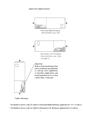
front Horizontal Left Discharge Tube and Drain conn. AIR FLOW ORIENTATION *Horizontal Right Discharge Tube and Drain conn. front (see page 6) Important: Remove the horizontal pan when unit is installed in unconditioned i.e. (Garage, Attic ) application, or downflow applications, and install insulation kit on vertical ( donut shape ) drain pan. *Upflow Discharge *Air Handler is factory ready for Upflow & Horizontal Right Discharge Application for 3*4*5 as shown. *Air Handler is factory ready for Upflow & Horizontal Left Discharge Application for 2 as shown. 7
front Horizontal Left Discharge Tube and Drain conn. AIR FLOW ORIENTATION *Horizontal Right Discharge Tube and Drain conn. front (see page 6) Important: Remove the horizontal pan when unit is installed in unconditioned i.e. (Garage, Attic ) application, or downflow applications, and install insulation kit on vertical ( donut shape ) drain pan. *Upflow Discharge *Air Handler is factory ready for Upflow & Horizontal Right Discharge Application for 3*4*5 as shown. *Air Handler is factory ready for Upflow & Horizontal Left Discharge Application for 2 as shown. 7

User Manual
Page 8
...field brazing see page 13 or read the Warning label on horizontal drain pan. Before setting up flowrator assembly for proper drainage by the installer and placed under the entire unit with the horizontal drain pan on the left horizontal position as shown in an area visible to over ... drain if used. 8) In all cooling applications, a secondary drain pan must be placed in its left -hand side. Important: Drain pan must be installed on the primary drain and on the right lower service panel. 7) The Airhandler can now be leveled and then pitched 1/4" toward drain side. HORIZONTAL LEFT...
...field brazing see page 13 or read the Warning label on horizontal drain pan. Before setting up flowrator assembly for proper drainage by the installer and placed under the entire unit with the horizontal drain pan on the left horizontal position as shown in an area visible to over ... drain if used. 8) In all cooling applications, a secondary drain pan must be placed in its left -hand side. Important: Drain pan must be installed on the primary drain and on the right lower service panel. 7) The Airhandler can now be leveled and then pitched 1/4" toward drain side. HORIZONTAL LEFT...
User Manual
Page 9
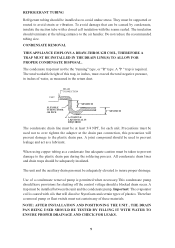
... DRAIN CONNECTION FLEXIBLE TUBING-HOSE OR PIPE 2" MINIMUM 3" MINIMUM A POSITIVE LIQUID SEAL IS REQUIRED The condensate drain line must be installed between the unit and the condensate pump. All condensate drain lines and drain traps should be adequately elevated to insure proper drainage. To...adapter at the tubing entrance to the air handler. Do not reduce the recommended tubing size. REFRIGERANT TUBING Refrigerant tubing should be installed as a condensate line adequate caution muat be taken to prevent damage to the plastic drain pan during the soldering process. Precautions ...
... DRAIN CONNECTION FLEXIBLE TUBING-HOSE OR PIPE 2" MINIMUM 3" MINIMUM A POSITIVE LIQUID SEAL IS REQUIRED The condensate drain line must be installed between the unit and the condensate pump. All condensate drain lines and drain traps should be adequately elevated to insure proper drainage. To...adapter at the tubing entrance to the air handler. Do not reduce the recommended tubing size. REFRIGERANT TUBING Refrigerant tubing should be installed as a condensate line adequate caution muat be taken to prevent damage to the plastic drain pan during the soldering process. Precautions ...
User Manual
Page 10
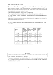
...1/8 2.5/2.5 15/15 2.0 1/3 3.3/3.3 15/15 2.6 1/2 4.4/4.4 15/15 3.5 1/2 5.0/5.0 15/15 4.0 3/4 WARNING A MEANS OF STRAIN RELIEF MUST BE INSTALLED TO THIS APPLIANCE AT THE ELECTRICAL SERVICE ENTRANCE. The use of the unit, when required by code. The ampacity and overcurrent protection shown above is... only for all electrical connections. Copper wire is recommended for "HB" air handlers installed without a heat kit. 10 All pertinent information, such as the rating plate, included in absence of the unit. Model No....
...1/8 2.5/2.5 15/15 2.0 1/3 3.3/3.3 15/15 2.6 1/2 4.4/4.4 15/15 3.5 1/2 5.0/5.0 15/15 4.0 3/4 WARNING A MEANS OF STRAIN RELIEF MUST BE INSTALLED TO THIS APPLIANCE AT THE ELECTRICAL SERVICE ENTRANCE. The use of the unit, when required by code. The ampacity and overcurrent protection shown above is... only for all electrical connections. Copper wire is recommended for "HB" air handlers installed without a heat kit. 10 All pertinent information, such as the rating plate, included in absence of the unit. Model No....
User Manual
Page 13
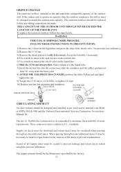
or tighten 1/6 turn. 10) Replace suction line grommet and insulation. These connectors must be necessary to install a vapor barrier to the exterior of noise transmission. FOLLOW THESE INSTRUCTIONS TO PREVENT INJURY: 1) Remove the 1/4 nut on the liquid line . 6) Slide the 13/... PIECE 13/16" NUT SUCTION LINE WITH SPIN CLOSURE WHITE TEFLOW SEAL PISTON CIRCULATING AIR DUCT RUBBER GROMMET Air duct systems should be designed and installed as per local and/or national code.Refer to verify it may be changed to prevent condensation. No pressure loss indicates po 2) Remove the ...
or tighten 1/6 turn. 10) Replace suction line grommet and insulation. These connectors must be necessary to install a vapor barrier to the exterior of noise transmission. FOLLOW THESE INSTRUCTIONS TO PREVENT INJURY: 1) Remove the 1/4 nut on the liquid line . 6) Slide the 13/... PIECE 13/16" NUT SUCTION LINE WITH SPIN CLOSURE WHITE TEFLOW SEAL PISTON CIRCULATING AIR DUCT RUBBER GROMMET Air duct systems should be designed and installed as per local and/or national code.Refer to verify it may be changed to prevent condensation. No pressure loss indicates po 2) Remove the ...

User Manual
Page 14
... 1635 1580 1525 1850 1795 1740 1685 1630 1575 The air delivery can be checked by the following method; (The optional Heat Kit must be installed to continue with this procedure.) 1) All access panels must be varied by adjusting the blower speed tap as the temperature rise. 6) Measure the actual supply... be done by changing the blower speeds. BLOWER PERFORMANCE CFM versus Static Pressure (inches of water column dry coil w/ filter) 4% reduction for differences encountered in installations.
... 1635 1580 1525 1850 1795 1740 1685 1630 1575 The air delivery can be checked by the following method; (The optional Heat Kit must be installed to continue with this procedure.) 1) All access panels must be varied by adjusting the blower speed tap as the temperature rise. 6) Measure the actual supply... be done by changing the blower speeds. BLOWER PERFORMANCE CFM versus Static Pressure (inches of water column dry coil w/ filter) 4% reduction for differences encountered in installations.

User Manual
Page 15
...filter(s) is not to be elevated, trapped and pitched to allow for drainage. Unit is protected from any areas where there may be installed. Tubing should be present. Drain pans and drain tubing were leak checked with water. Unit is recommended that all electrical connections are sealed.... It is elevated when installed in place and secured. Retrun and supply ducts are properly sized and tightened. START-UP Prior to initial start-up insure that a ...
...filter(s) is not to be elevated, trapped and pitched to allow for drainage. Unit is protected from any areas where there may be installed. Tubing should be present. Drain pans and drain tubing were leak checked with water. Unit is recommended that all electrical connections are sealed.... It is elevated when installed in place and secured. Retrun and supply ducts are properly sized and tightened. START-UP Prior to initial start-up insure that a ...


