
Installation Instructions
Page 6
Refrigerant circuit AU282FHERA Ta one-way valve Tc strainer PMV strainer Te accumulator liquid pipe strainer SV2 outdoor 4-way valve gas pipe strainer oil segregator OP strainer oil return capillary Ts Td compressor LP gas-liquid segregator 图例 connected disconnected Tc2 PMV Ta indoor Tc1 06 4.
Refrigerant circuit AU282FHERA Ta one-way valve Tc strainer PMV strainer Te accumulator liquid pipe strainer SV2 outdoor 4-way valve gas pipe strainer oil segregator OP strainer oil return capillary Ts Td compressor LP gas-liquid segregator 图例 connected disconnected Tc2 PMV Ta indoor Tc1 06 4.

Installation Instructions
Page 7
AU48NFIERA AU60NFIERA Ta 室外 HEX one-way valve Te Tc strainer PMV strainer accumulator strainer SV2 liquid pipe 4-way valve gas pipe strainer SV1 strainer oil segregator strainer OP oil return capillary Td Ts compressor LP gas-liquid segregator legend outdoor connected disconnected PMV Tc2 Ta Tc1 indoor 07
AU48NFIERA AU60NFIERA Ta 室外 HEX one-way valve Te Tc strainer PMV strainer accumulator strainer SV2 liquid pipe 4-way valve gas pipe strainer SV1 strainer oil segregator strainer OP oil return capillary Td Ts compressor LP gas-liquid segregator legend outdoor connected disconnected PMV Tc2 Ta Tc1 indoor 07

Installation Instructions
Page 11
6. Wiring diagram AU28: STARTUP CAPACITOR FAN MOTOR HEATER 4-WAY VALVE SPRAY VALVE COMP CN14 4-WAY SV2 CON2 ACFAN1 HEATER CON3 W VU R WB CN1 HP CN2 LP control board CN5 TC CN4 TE CN3 TD CN6 TS W CN7 TA MODULE_COM PMV CN10 CN8 B CN19 (OUT/IN_COM)CN21 0150503461 CN5(U) CN6(V) CN7(W) I P M CN9 CN3 CN4 CN11CN2 B W CN1 W B ISPM TEMPERATURE SENSOR COM CN3 Y/G NO CN4(PTC)CN1 NOISE FILTER CN5 CN6 CN2 W:white R:red B:black BL:blue Y:yellow G:green P M V P Q communication wire with indoor unit WB Y/G LN POWER SUPPLY 11
6. Wiring diagram AU28: STARTUP CAPACITOR FAN MOTOR HEATER 4-WAY VALVE SPRAY VALVE COMP CN14 4-WAY SV2 CON2 ACFAN1 HEATER CON3 W VU R WB CN1 HP CN2 LP control board CN5 TC CN4 TE CN3 TD CN6 TS W CN7 TA MODULE_COM PMV CN10 CN8 B CN19 (OUT/IN_COM)CN21 0150503461 CN5(U) CN6(V) CN7(W) I P M CN9 CN3 CN4 CN11CN2 B W CN1 W B ISPM TEMPERATURE SENSOR COM CN3 Y/G NO CN4(PTC)CN1 NOISE FILTER CN5 CN6 CN2 W:white R:red B:black BL:blue Y:yellow G:green P M V P Q communication wire with indoor unit WB Y/G LN POWER SUPPLY 11

Installation Instructions
Page 12
AU48/60N: 0150502942 CN21OUT/IN_COM CN7 TA CN6 TS CN8 CN5 TC PMV CN4 TE AB CN24 CN11 LED-DISPLAY MODULE_COM U CON3 MOD BUS V W SCP2 SCN SCP1 CN3 TD P CN2 LP B W P CN1 HP ACL (DOWN) (UP) ACFAN2 ACFAN1 ACN CN19 CN18 CN17 CN25 CN16 CN15 CN14 +- SV2 SV1 4WV M M HEATER W BB B B PTC Y/G E / N / L3/ L2/ L1/ NOISE FILTER E N L3 L2 L1 BL B W R LN R S BT B RW W:white B:black Y:yellow R:red BL:blue G:green PQ communication wire with indoor unit Y/G RSTN 1 23 4 6 5 COMP 12
AU48/60N: 0150502942 CN21OUT/IN_COM CN7 TA CN6 TS CN8 CN5 TC PMV CN4 TE AB CN24 CN11 LED-DISPLAY MODULE_COM U CON3 MOD BUS V W SCP2 SCN SCP1 CN3 TD P CN2 LP B W P CN1 HP ACL (DOWN) (UP) ACFAN2 ACFAN1 ACN CN19 CN18 CN17 CN25 CN16 CN15 CN14 +- SV2 SV1 4WV M M HEATER W BB B B PTC Y/G E / N / L3/ L2/ L1/ NOISE FILTER E N L3 L2 L1 BL B W R LN R S BT B RW W:white B:black Y:yellow R:red BL:blue G:green PQ communication wire with indoor unit Y/G RSTN 1 23 4 6 5 COMP 12

Installation Instructions
Page 13
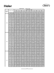
Capacity table outdoor capacity factor temp. (℃DB) 5 10 15 20 130% 25 30 35 41 43 5 10 15 20 120% 25 30 35 41 43 5 10 15 20 110% 25 ... 6.1 1.72 6.1 2.02 6.1 2.17 5.6 0.87 5.6 0.88 5.6 0.92 5.6 0.96 5.6 1.08 5.6 1.28 5.6 1.51 5.6 1.77 5.6 1.93 5.0 0.74 5.0 0.78 5.0 0.82 5.0 0.86 5.0 0.94 5.0 1.12 5.0 1.32 5.0 1.53 5.0 1.70 4.4 0.66 4.4 0.69 4.4 0.72 AU282FHERA cooling mode indoor temp. (℃WB) 16(℃) 18(℃) 19(℃) 20(℃) TC PI TC PI TC PI TC PI KW KW KW KW KW KW KW...
Capacity table outdoor capacity factor temp. (℃DB) 5 10 15 20 130% 25 30 35 41 43 5 10 15 20 120% 25 30 35 41 43 5 10 15 20 110% 25 ... 6.1 1.72 6.1 2.02 6.1 2.17 5.6 0.87 5.6 0.88 5.6 0.92 5.6 0.96 5.6 1.08 5.6 1.28 5.6 1.51 5.6 1.77 5.6 1.93 5.0 0.74 5.0 0.78 5.0 0.82 5.0 0.86 5.0 0.94 5.0 1.12 5.0 1.32 5.0 1.53 5.0 1.70 4.4 0.66 4.4 0.69 4.4 0.72 AU282FHERA cooling mode indoor temp. (℃WB) 16(℃) 18(℃) 19(℃) 20(℃) TC PI TC PI TC PI TC PI KW KW KW KW KW KW KW...

Installation Instructions
Page 19
capacity factor 130 120 110 outdoor temp. ℃DB -14.7 -12.6 -10.5 -9.5 -8.5 -7.0 -5.0 -3.0 0.0 3.0 5.0 7.0 9.0 11.0 13.0 15.0 19.0 21.0 -14.7 -12.6 -10.5 -9.5 -8.5 -7.0 -5.0 -3.0 0.0 3.0 5.0 7.0 9.0 11.0 13.0 15.0 19.0 21.0 -14.7 -12.6 -10.5 -9.5 -8.5 -7.0 -5.0 -3.0 0.0 3.0 5.0... 1.96 7.0 2.03 7.2 2.07 7.4 2.10 7.6 2.14 8.0 2.20 8.3 2.24 8.8 2.31 9.4 2.37 9.7 2.41 10.0 2.43 10.3 2.47 10.7 2.50 11.0 2.52 11.3 2.54 AU282FHERA heating mode indoor temp.℃DB 18.0 20.0 21.0 TC PI TC PI TC PI KW KW KW KW KW KW 6.4 1.71 6.4 1.81 6.4 1.86 6.7 1.81 6.7 1.90 6.7 1.94 7.0 1.89 7.0 1.98...
capacity factor 130 120 110 outdoor temp. ℃DB -14.7 -12.6 -10.5 -9.5 -8.5 -7.0 -5.0 -3.0 0.0 3.0 5.0 7.0 9.0 11.0 13.0 15.0 19.0 21.0 -14.7 -12.6 -10.5 -9.5 -8.5 -7.0 -5.0 -3.0 0.0 3.0 5.0 7.0 9.0 11.0 13.0 15.0 19.0 21.0 -14.7 -12.6 -10.5 -9.5 -8.5 -7.0 -5.0 -3.0 0.0 3.0 5.0... 1.96 7.0 2.03 7.2 2.07 7.4 2.10 7.6 2.14 8.0 2.20 8.3 2.24 8.8 2.31 9.4 2.37 9.7 2.41 10.0 2.43 10.3 2.47 10.7 2.50 11.0 2.52 11.3 2.54 AU282FHERA heating mode indoor temp.℃DB 18.0 20.0 21.0 TC PI TC PI TC PI KW KW KW KW KW KW 6.4 1.71 6.4 1.81 6.4 1.86 6.7 1.81 6.7 1.90 6.7 1.94 7.0 1.89 7.0 1.98...

Installation Instructions
Page 22
capacity factor 130 120 110 outdoor temp. ℃DB -14.7 -12.6 -10.5 -9.5 -8.5 -7.0 -5.0 -3.0 0.0 3.0 5.0 7.0 9.0 11.0 13.0 15.0 19.0 21.0 -14.7 -12.6 -10.5 -9.5 -8.5 -7.0 -5.0 -3.0 0.0 3.0 5.0 7.0 9.0 11.0 13.0 15.0 19.0 21.0 -14.7 -12.6 -10.5 -9.5 -8.5 -7.0 -5.0 -3.0 0.0 3.0 5.0 7.0 9.0 11.0 13.0 ℃WB -... 12.7 4.22 13.0 4.27 13.4 4.36 14.0 4.49 14.6 4.57 15.5 4.70 16.5 4.83 16.9 4.92 17.5 4.96 18.1 5.04 18.7 5.09 19.3 5.13 AU48NFIERA heating mode indoor temp.℃DB 18.0 20.0 21.0 TC PI TC PI TC PI KW KW KW KW KW KW 11.1 3.49 11.1 3.68 11.1 3.78 11.8 3.68...
capacity factor 130 120 110 outdoor temp. ℃DB -14.7 -12.6 -10.5 -9.5 -8.5 -7.0 -5.0 -3.0 0.0 3.0 5.0 7.0 9.0 11.0 13.0 15.0 19.0 21.0 -14.7 -12.6 -10.5 -9.5 -8.5 -7.0 -5.0 -3.0 0.0 3.0 5.0 7.0 9.0 11.0 13.0 15.0 19.0 21.0 -14.7 -12.6 -10.5 -9.5 -8.5 -7.0 -5.0 -3.0 0.0 3.0 5.0 7.0 9.0 11.0 13.0 ℃WB -... 12.7 4.22 13.0 4.27 13.4 4.36 14.0 4.49 14.6 4.57 15.5 4.70 16.5 4.83 16.9 4.92 17.5 4.96 18.1 5.04 18.7 5.09 19.3 5.13 AU48NFIERA heating mode indoor temp.℃DB 18.0 20.0 21.0 TC PI TC PI TC PI KW KW KW KW KW KW 11.1 3.49 11.1 3.68 11.1 3.78 11.8 3.68...
Installation Instructions
Page 25
capacity factor 130 120 110 outdoor temp. ℃DB -14.7 -12.6 -10.5 -9.5 -8.5 -7.0 -5.0 -3.0 0.0 3.0 5.0 7.0 9.0 11.0 13.0 15.0 19.0 21.0 -14.7 -12.6 -10.5 -9.5 -8.5 -7.0 -5.0 -3.0 0.0 3.0 5.0 7.0 9.0 11.0 13.0 15.0 19.0 21.0 -14.7 -12.6 -10.5 -9.5 -8.5 -7.0 -5.0 -3.0 0.0 3.0 5.0 7.0 9.0 11.0 13.0 ℃WB -....1 4.77 14.5 4.86 14.8 4.92 15.3 5.02 16.0 5.17 16.6 5.26 17.7 5.41 18.8 5.56 19.4 5.66 20.0 5.71 20.6 5.80 21.4 5.85 22.0 5.90 AU60NFIERA heating mode indoor temp.℃DB 18.0 20.0 21.0 TC PI TC PI TC PI KW KW KW KW KW KW 12.7 4.02 12.7 4.24 12.7 4.35 13.4 4.24...
capacity factor 130 120 110 outdoor temp. ℃DB -14.7 -12.6 -10.5 -9.5 -8.5 -7.0 -5.0 -3.0 0.0 3.0 5.0 7.0 9.0 11.0 13.0 15.0 19.0 21.0 -14.7 -12.6 -10.5 -9.5 -8.5 -7.0 -5.0 -3.0 0.0 3.0 5.0 7.0 9.0 11.0 13.0 15.0 19.0 21.0 -14.7 -12.6 -10.5 -9.5 -8.5 -7.0 -5.0 -3.0 0.0 3.0 5.0 7.0 9.0 11.0 13.0 ℃WB -....1 4.77 14.5 4.86 14.8 4.92 15.3 5.02 16.0 5.17 16.6 5.26 17.7 5.41 18.8 5.56 19.4 5.66 20.0 5.71 20.6 5.80 21.4 5.85 22.0 5.90 AU60NFIERA heating mode indoor temp.℃DB 18.0 20.0 21.0 TC PI TC PI TC PI KW KW KW KW KW KW 12.7 4.02 12.7 4.24 12.7 4.35 13.4 4.24...

Installation Instructions
Page 41
...`shnm vhqd vhkk ad hmsdqedqdc sn b`trd `amnql`k4 Note: When one wired controller controls multiple indoors, the connected indoor units must use the common phase of power source, or the communication will be abnormal.For example, the power source is L1,L2,L3,and N, all the indoor units must use L1/N or L2/N or L3/N. 42 R]e]a[ flfgY` .7/ Tnvdq vhqhmf ehftqd ntscnnq...
...`shnm vhqd vhkk ad hmsdqedqdc sn b`trd `amnql`k4 Note: When one wired controller controls multiple indoors, the connected indoor units must use the common phase of power source, or the communication will be abnormal.For example, the power source is L1,L2,L3,and N, all the indoor units must use L1/N or L2/N or L3/N. 42 R]e]a[ flfgY` .7/ Tnvdq vhqhmf ehftqd ntscnnq...

Installation Instructions
Page 43
.9/ Gnlltmhb`shnm vhqd enq vhqdc bnmsqnkkdq vhqd kdmfsg.l/ vhqd rodb vhqd kdmfsg.l/ vhqd rodb 7766 :766 `mc 4866 :866 `mc 4966 649ll8 9.93bnqd/ rghdkcdc vhqd 64;ll8 9 .93bnqd/ rghdkcdc vhqd 64=;ll8 9 .93bnqd/ rghdkcdc vhqd ~066 `mc B166 ~166 `mc B366 748;ll8 9.93bnqd/ rghdkcdc vhqd 8ll8 9 .93bnqd/ rghdkcdc vhqd `4 Wghdkcdc k`xdq ne bnlltmhb`shnm vhqd ltrs ad d`qsgdc `s nmd dmc4 a4 Xgd sns`k kdmfsg b`mmns dwbddc 3^
.9/ Gnlltmhb`shnm vhqd enq vhqdc bnmsqnkkdq vhqd kdmfsg.l/ vhqd rodb vhqd kdmfsg.l/ vhqd rodb 7766 :766 `mc 4866 :866 `mc 4966 649ll8 9.93bnqd/ rghdkcdc vhqd 64;ll8 9 .93bnqd/ rghdkcdc vhqd 64=;ll8 9 .93bnqd/ rghdkcdc vhqd ~066 `mc B166 ~166 `mc B366 748;ll8 9.93bnqd/ rghdkcdc vhqd 8ll8 9 .93bnqd/ rghdkcdc vhqd `4 Wghdkcdc k`xdq ne bnlltmhb`shnm vhqd ltrs ad d`qsgdc `s nmd dmc4 a4 Xgd sns`k kdmfsg b`mmns dwbddc 3^
Installation Instructions
Page 63
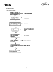
... wire and power cable set ? yes Is there external signal interference? no wiring Separately yes Eliminate interference yes Replace indoor PCB no Reconnect securely connected? no Use shielded wire. Without repetition? yes no Is indoor mainboard poorly welded? yes Is shielded wire used for communication? Make necessary replacement 63 Changeable? yes Is indoor unit address properly set separately? Troubleshooting: 1.Communication failure Is number of indoor and outdoor units no Check outdoor...
... wire and power cable set ? yes Is there external signal interference? no wiring Separately yes Eliminate interference yes Replace indoor PCB no Reconnect securely connected? no Use shielded wire. Without repetition? yes no Is indoor mainboard poorly welded? yes Is shielded wire used for communication? Make necessary replacement 63 Changeable? yes Is indoor unit address properly set separately? Troubleshooting: 1.Communication failure Is number of indoor and outdoor units no Check outdoor...

Installation Instructions
Page 64
... connected? yes Normal no EEPROM chip installed firmly Reinstall in right direction yes Is the PCB poorly w elded? no Check the wiring condition yes no Check PCB and replace 4. yes Replace chip no Re-wire as the wiring diagram Replace the power module 64 Over current protection Check if the compressor current yes Check the system, fan motor, is broken? 2.Sensor failure Are connectors of...
... connected? yes Normal no EEPROM chip installed firmly Reinstall in right direction yes Is the PCB poorly w elded? no Check the wiring condition yes no Check PCB and replace 4. yes Replace chip no Re-wire as the wiring diagram Replace the power module 64 Over current protection Check if the compressor current yes Check the system, fan motor, is broken? 2.Sensor failure Are connectors of...

Installation Instructions
Page 65
... and recharge no Check fan motor and capacitor yes Is filter or heat exchanger dirty? Is there air in good condition? Does outdoor fan work properly during cooling cycle? Check 1) Connector 2) Winding resistance 3) Valve 4) Mainboard yes no yes Adjustment or replacement When TD is too much or lack. no Repair outdoor EEV Is actual discharging temperature detected by pass circuit can work properly during heating cycle? yes no Open the stop...
... and recharge no Check fan motor and capacitor yes Is filter or heat exchanger dirty? Is there air in good condition? Does outdoor fan work properly during cooling cycle? Check 1) Connector 2) Winding resistance 3) Valve 4) Mainboard yes no yes Adjustment or replacement When TD is too much or lack. no Repair outdoor EEV Is actual discharging temperature detected by pass circuit can work properly during heating cycle? yes no Open the stop...

Installation Instructions
Page 66
... Are connectors of outdoor unit open? yes Is piping twisted or deformed? yes Are stop valve yes Repair or replacement if outdoor fan motor work properly during cooling cycle? no no Check fan motor or indoor EEV yes Is filter or heat exchanger dirty? no Replace high pressure switch pressure gauge above 3MPa? Is reading of discharging pipe pressure gauge oscillatory? and if indoor fan motor and indoor EEV work properly during heating cycle? yes Is...
... Are connectors of outdoor unit open? yes Is piping twisted or deformed? yes Are stop valve yes Repair or replacement if outdoor fan motor work properly during cooling cycle? no no Check fan motor or indoor EEV yes Is filter or heat exchanger dirty? no Replace high pressure switch pressure gauge above 3MPa? Is reading of discharging pipe pressure gauge oscillatory? and if indoor fan motor and indoor EEV work properly during heating cycle? yes Is...

Installation Instructions
Page 67
... yes yes Cleaning If refrigerant circuit is leak? yes Is low side pressure switch activated? no Adjust and maintain no Replace low pressure switch yes If outdoor stop valve yes Is piping twisted or deformed? no Do outdoor fan and PMV work properly during cooling cycle? 7 . yes no Check and reconnect no Repair fan motor and EEV yes If the filter and heat exchanger are open totally Open stop valves of refrigerant? Low...
... yes yes Cleaning If refrigerant circuit is leak? yes Is low side pressure switch activated? no Adjust and maintain no Replace low pressure switch yes If outdoor stop valve yes Is piping twisted or deformed? no Do outdoor fan and PMV work properly during cooling cycle? 7 . yes no Check and reconnect no Repair fan motor and EEV yes If the filter and heat exchanger are open totally Open stop valves of refrigerant? Low...

Installation Instructions
Page 68
... control wire is in the range of refrigerant; if the system is normal; Suction temperature protection Measure if the actual air return temperature is over 40degree yes no Check the suction temperature Check the system: if the stop valve is clogged or leaks 9. if EEV works normally; Communication with power module failure Check if PCB is electrified with the power module no Replace power...
... control wire is in the range of refrigerant; if the system is normal; Suction temperature protection Measure if the actual air return temperature is over 40degree yes no Check the suction temperature Check the system: if the stop valve is clogged or leaks 9. if EEV works normally; Communication with power module failure Check if PCB is electrified with the power module no Replace power...


