Operation Manual
Page 2
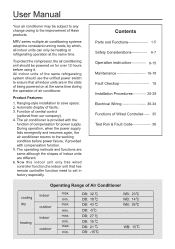
...wired controller function,the indoor unit that has remote controller function need to ensure that all indoor units can only be heating or refrigerating operation at the same time during the operation of Haier products. Contents Parts and Functions- 1-5 Safety Considerations 6-7 Operation instruction- 8-15 Maintenance 16-18 Fault Checkup 19 Installation Procedures- 20-29 Electrical Wiring 30-34 Functions of Wired Controller 35 Test Run & Fault Code 36 cooling dry heating Operating Range of faults; 3. Automatic display of Air Conditioner indoor outdoor indoor...
...wired controller function,the indoor unit that has remote controller function need to ensure that all indoor units can only be heating or refrigerating operation at the same time during the operation of Haier products. Contents Parts and Functions- 1-5 Safety Considerations 6-7 Operation instruction- 8-15 Maintenance 16-18 Fault Checkup 19 Installation Procedures- 20-29 Electrical Wiring 30-34 Functions of Wired Controller 35 Test Run & Fault Code 36 cooling dry heating Operating Range of faults; 3. Automatic display of Air Conditioner indoor outdoor indoor...

Operation Manual
Page 4
... E TIMER • TEMP • TI0ME±) ET RECOVERY OOFNF88 . 88 REACOVOERY CHECK FILTER DAILy • (m) NORMAL RESET 0 nnnnn Timing switch It is as follows: No display-air change (automatic)-air change (RECOVERY)-air change function. The mode is used to control oxygen function and negative ion DE F N S ING AUTO FAN ONLY COOL DRY HEAT TES FAN AUTO HIGH MED LOW FIX CENTRAL OPERATION STANDBY PRE-HEAT DEFROST FILTER 1EALTH) UNIT NO. and is used for changing set temperature Time switch It...
... E TIMER • TEMP • TI0ME±) ET RECOVERY OOFNF88 . 88 REACOVOERY CHECK FILTER DAILy • (m) NORMAL RESET 0 nnnnn Timing switch It is as follows: No display-air change (automatic)-air change (RECOVERY)-air change function. The mode is used to control oxygen function and negative ion DE F N S ING AUTO FAN ONLY COOL DRY HEAT TES FAN AUTO HIGH MED LOW FIX CENTRAL OPERATION STANDBY PRE-HEAT DEFROST FILTER 1EALTH) UNIT NO. and is used for changing set temperature Time switch It...

Operation Manual
Page 5
... FILTER RESET 0 C ON/OFF 0 ) Filter screen warning sign When the sign is shown to reflect no need to run,"DEMAND" will be displayed, or show alarm , "standby" is shown, please clean the filter screen Air change display Wind swing display Remarks •The models in the temperature zone. Display the setting speed Running mode display Show the selected mode Health function display Unit number display Centralized adress display System adress display Temperature display Display the room temperature, setting temperature, and unit number AUTO FAN ONLY COOL DRY HEAT...
... FILTER RESET 0 C ON/OFF 0 ) Filter screen warning sign When the sign is shown to reflect no need to run,"DEMAND" will be displayed, or show alarm , "standby" is shown, please clean the filter screen Air change display Wind swing display Remarks •The models in the temperature zone. Display the setting speed Running mode display Show the selected mode Health function display Unit number display Centralized adress display System adress display Temperature display Display the room temperature, setting temperature, and unit number AUTO FAN ONLY COOL DRY HEAT...

Operation Manual
Page 6
....LIGHT Button Used to light the control panel 12.LOCK Button Used to select Code A or B, Normally at Code A. As you can press the FILTER button for TIMER,SLEEP and SWING state). 4.Operation MODE Button Used to start or stop. if you press it again, lock state will be cleaned, you cann't controll the indoor unit, please change the Code to B. 10.RESET Button Press this button once, auto swing will draw in the present position. 3.Power ON/OFF Button Used for unit to...
....LIGHT Button Used to light the control panel 12.LOCK Button Used to select Code A or B, Normally at Code A. As you can press the FILTER button for TIMER,SLEEP and SWING state). 4.Operation MODE Button Used to start or stop. if you press it again, lock state will be cleaned, you cann't controll the indoor unit, please change the Code to B. 10.RESET Button Press this button once, auto swing will draw in the present position. 3.Power ON/OFF Button Used for unit to...

Operation Manual
Page 7
... PM stop flashing, while clock starts working. When throw away the waste batteries, please perform in this manual. 26.SIGNAL SENDING Display 27.Code B of the same type, press the Reset button (marked 1) with the local regulation. Each press the time will increase or decrease quickly. 3.Press "SET" button to set . 31.Operation MODE Disp ay AUTO RUN COOL RUN DRY RUN HEAT RUN FAN RUN V 40 a O 32.SLEEP State Display 33...
... PM stop flashing, while clock starts working. When throw away the waste batteries, please perform in this manual. 26.SIGNAL SENDING Display 27.Code B of the same type, press the Reset button (marked 1) with the local regulation. Each press the time will increase or decrease quickly. 3.Press "SET" button to set . 31.Operation MODE Disp ay AUTO RUN COOL RUN DRY RUN HEAT RUN FAN RUN V 40 a O 32.SLEEP State Display 33...
Operation Manual
Page 8
... to avoid condensation. In addition, heat preservation should be taken to the user for installation and repair. If not, water leakage, electric shocks, fire accidents or refrigerant leakage might cause the dropdown of the machine. • Specific cables should be effectively grounded. If the refrigerant gas leaks in accordance with insufficient support strength might be caused. • Don't drain the water from being powered. •...
... to avoid condensation. In addition, heat preservation should be taken to the user for installation and repair. If not, water leakage, electric shocks, fire accidents or refrigerant leakage might cause the dropdown of the machine. • Specific cables should be effectively grounded. If the refrigerant gas leaks in accordance with insufficient support strength might be caused. • Don't drain the water from being powered. •...
Operation Manual
Page 9
... air conditioner, which may cause electric shock. OO j2 0 • Check the mount table of the air conditioner for damage for the preservation of storage. • 3-minute protection To protect the unit, compressor can be supervised to ensure that of the outdoor unit stops running and switch off the manual power switch when cleaning the unit. • During the operation of 0 controller to the indoor unit and the wired controller. During defrosting, the fan...
... air conditioner, which may cause electric shock. OO j2 0 • Check the mount table of the air conditioner for damage for the preservation of storage. • 3-minute protection To protect the unit, compressor can be supervised to ensure that of the outdoor unit stops running and switch off the manual power switch when cleaning the unit. • During the operation of 0 controller to the indoor unit and the wired controller. During defrosting, the fan...
Operation Manual
Page 10
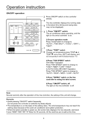
.... Do not press line controller or switches by sharp objects. • The temperature is off . Press "ON/OFF" switch. Press "mode"switch to change to change . Operation instruction ON/OFF operation CM COOL 11723 1 OPERATION HIGH MODE FAN SWING HEALTH • TEMP • 2gt ROOMTEMP. CLOCK ionu.l 0I37 CLOCK • TIME • TIMER SET RECOVERY CHECK C=0= FILTER ) 1 RESET 0 ON/OFF O 2 Press ON/OFF switch on line controller directly 4 The line controller displays the running state...
.... Do not press line controller or switches by sharp objects. • The temperature is off . Press "ON/OFF" switch. Press "mode"switch to change to change . Operation instruction ON/OFF operation CM COOL 11723 1 OPERATION HIGH MODE FAN SWING HEALTH • TEMP • 2gt ROOMTEMP. CLOCK ionu.l 0I37 CLOCK • TIME • TIMER SET RECOVERY CHECK C=0= FILTER ) 1 RESET 0 ON/OFF O 2 Press ON/OFF switch on line controller directly 4 The line controller displays the running state...

Operation Manual
Page 12
... timing display. The display changes with the following sequence: rON OFF-P-°ONFF OFF -I TIMER SET RECOVERY C iii=r 5D CH CK FIL ER RESET C nnnnn ON/OFF 0 3 2 Press "ON/OFF" switch firstly, and set time has elapsed, the unit starts. Cancel timing If you press " • " switch. CM COOL 11723 1 OPERATION HIGH MODE FAN SWING HEALTH (=IIM • TEMP CLOCK • TIME • 2Eic ROOM TEMP. The setting time...
... timing display. The display changes with the following sequence: rON OFF-P-°ONFF OFF -I TIMER SET RECOVERY C iii=r 5D CH CK FIL ER RESET C nnnnn ON/OFF 0 3 2 Press "ON/OFF" switch firstly, and set time has elapsed, the unit starts. Cancel timing If you press " • " switch. CM COOL 11723 1 OPERATION HIGH MODE FAN SWING HEALTH (=IIM • TEMP CLOCK • TIME • 2Eic ROOM TEMP. The setting time...

Operation Manual
Page 13
... OFF ON Function description set as the slave controller set as the master controller standard controller air handler controller visible room temperature invisible room temperature Unavailable 26° lock available 26° lock Sensor of the controller Sensor in the whole group are displayed, the mode will quit automatically. If the wire controller is powered off , press [CHECK] button, enter the malfunction-querying mode of all indoor units in the unit unavailable SW1-7 Factory...
... OFF ON Function description set as the slave controller set as the master controller standard controller air handler controller visible room temperature invisible room temperature Unavailable 26° lock available 26° lock Sensor of the controller Sensor in the whole group are displayed, the mode will quit automatically. If the wire controller is powered off , press [CHECK] button, enter the malfunction-querying mode of all indoor units in the unit unavailable SW1-7 Factory...
Operation Manual
Page 14
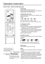
Operation instruction AUTO, COOL , HEAT and DRY Operation (1) Unit start Press ON/OFF button, the unit starts. Previous operation status appears on LCD. if the button is not displayed on LCD (except for A TIMER,SLEEP and SWING setting) 2qc TEMP • 3 ON 3 S NG 5 1 4 MODE SLEEP 2 TH FRESH fn SET TIMER HIGHISO ,_CD CV), 0 FILTER cllE- COOL operation starts NOTE: when room temp.is pressed, the setting temperature increases by 1°C, if the button is lower than temperature On reaching temp.setting setting, unit will only run FAN operation. +2°C, unit ...
Operation instruction AUTO, COOL , HEAT and DRY Operation (1) Unit start Press ON/OFF button, the unit starts. Previous operation status appears on LCD. if the button is not displayed on LCD (except for A TIMER,SLEEP and SWING setting) 2qc TEMP • 3 ON 3 S NG 5 1 4 MODE SLEEP 2 TH FRESH fn SET TIMER HIGHISO ,_CD CV), 0 FILTER cllE- COOL operation starts NOTE: when room temp.is pressed, the setting temperature increases by 1°C, if the button is lower than temperature On reaching temp.setting setting, unit will only run FAN operation. +2°C, unit ...
Operation Manual
Page 15
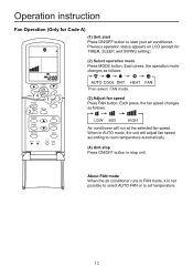
...button to stop unit. About FAN mode When the air conditioner runs in AUTO mode, the unit will run at the selected fan speed. Each press, the fan speed changes as follows: mode AUTO COOL DRY HEAT Then select FAN mode. gild AM 12:011:, C ) TEMP c) N 4 SWING MODE 1 3 EP 2 TH FRESH (--) TIMER ' HIGH/SO C---) C*) C) EAT FILTER H ,!5 ( LIGH5T5 RESET CODE • • (2) Select operation mode Press MODE button. Previous operation status appears on LCD (except for Code A) f A (1) Unit start Press ON/OFF button to set temperature. 13 Operation instruction...
...button to stop unit. About FAN mode When the air conditioner runs in AUTO mode, the unit will run at the selected fan speed. Each press, the fan speed changes as follows: mode AUTO COOL DRY HEAT Then select FAN mode. gild AM 12:011:, C ) TEMP c) N 4 SWING MODE 1 3 EP 2 TH FRESH (--) TIMER ' HIGH/SO C---) C*) C) EAT FILTER H ,!5 ( LIGH5T5 RESET CODE • • (2) Select operation mode Press MODE button. Previous operation status appears on LCD (except for Code A) f A (1) Unit start Press ON/OFF button to set temperature. 13 Operation instruction...
Operation Manual
Page 16
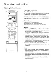
... downward will drop water. Adjusting them by remote controller. • In COOL or DRY mode, do not leave the louver in downward position for a better air circulation • As in air conditioner's abnormally running. C ) TEMP ON OFF MODE HEALTH FRESH C)( ) c ) .., FAN Apm.• n CLOCK ci) SET TIMER s O O FILTER r HIGH/SO CD HEAT RESET CODE • • LIGHT LOCK O O Adjusting air flow direction Press SWING button. If the louver work abnormally, stop unit, restart and adjust...
... downward will drop water. Adjusting them by remote controller. • In COOL or DRY mode, do not leave the louver in downward position for a better air circulation • As in air conditioner's abnormally running. C ) TEMP ON OFF MODE HEALTH FRESH C)( ) c ) .., FAN Apm.• n CLOCK ci) SET TIMER s O O FILTER r HIGH/SO CD HEAT RESET CODE • • LIGHT LOCK O O Adjusting air flow direction Press SWING button. If the louver work abnormally, stop unit, restart and adjust...
Operation Manual
Page 21
... starting operation, during refrigerating operation, cold air may make the cracking sound, which is a power failure. Under the following when consigning repair service: Symptoms Reasons • Water flow sound • Cracking sound Water flow sound can be operated after power failure, turn on the manual indicator power switch and the operating indicator flashes. Check if the setting of wind quantity is working automatically Check if it to the refrigerating or heating mode and the operation...
... starting operation, during refrigerating operation, cold air may make the cracking sound, which is a power failure. Under the following when consigning repair service: Symptoms Reasons • Water flow sound • Cracking sound Water flow sound can be operated after power failure, turn on the manual indicator power switch and the operating indicator flashes. Check if the setting of wind quantity is working automatically Check if it to the refrigerating or heating mode and the operation...

Operation Manual
Page 23
...(decorated board) 890mm(ceiling hole) 840mm(indoor unit) 780mm(hoiting stud gar) E cO O o Note: Before suspending the indoor unit, select the installation location according to the piping and wiring in the ceiling, and determine the lead direction of the indoor unit and fix it according to the requirements in the room, lead wire of line control to the locations of piping and wiring. • Confirm the size of the piping. Location Relationship...
...(decorated board) 890mm(ceiling hole) 840mm(indoor unit) 780mm(hoiting stud gar) E cO O o Note: Before suspending the indoor unit, select the installation location according to the piping and wiring in the ceiling, and determine the lead direction of the indoor unit and fix it according to the requirements in the room, lead wire of line control to the locations of piping and wiring. • Confirm the size of the piping. Location Relationship...
Operation Manual
Page 24
... situation with water, as to the schematic drawing at the lower part as an example. Check if the 4 angles of indoor unit, and append the rim to the ceiling to the overall drawing of the unit. (3) Perform Step 4 and 5 in drainage pump and a floater switch. Use the level meter to secure the foot. (2) Adjust the height and location of the air conditioner. Make...
... situation with water, as to the schematic drawing at the lower part as an example. Check if the 4 angles of indoor unit, and append the rim to the ceiling to the overall drawing of the unit. (3) Perform Step 4 and 5 in drainage pump and a floater switch. Use the level meter to secure the foot. (2) Adjust the height and location of the air conditioner. Make...

Operation Manual
Page 32
... be a U-type elbow and fastened with auxiliary electrically heating function, the live wire and plug N connected to null wire while C) should be connected to the installation instruction. Main Unit of Outdoor Sub Unit 1 of Outdoor Sub Unit 2 of the mains line is not sufficient. 0 • During arranging the wiring layout, specified cables should be used . Indoor & outdoor units should be equipped with specific mains circuit by users. Indoor units must be used as below...
... be a U-type elbow and fastened with auxiliary electrically heating function, the live wire and plug N connected to null wire while C) should be connected to the installation instruction. Main Unit of Outdoor Sub Unit 1 of Outdoor Sub Unit 2 of the mains line is not sufficient. 0 • During arranging the wiring layout, specified cables should be used . Indoor & outdoor units should be equipped with specific mains circuit by users. Indoor units must be used as below...

Operation Manual
Page 34
Electrical Wiring The combination of multiple indoor units can be controlled by wired controller or remote controller. X Switching Mode of Line-Controlled Main Unit/ Line-Controlled Sub Units/ Remote-Controlled Types can be used for the power line of indoor unit, the wiring between indoor and outdoor units as well as the wiring between indoor units: Items Total Current of remote control OFF Signal Terminals A,B,C are connected to wired controller B,C are connected to wired controller A,B,C are set to wired controller Note:AB*MCERA. controlled type before delivery The wiring ...
Electrical Wiring The combination of multiple indoor units can be controlled by wired controller or remote controller. X Switching Mode of Line-Controlled Main Unit/ Line-Controlled Sub Units/ Remote-Controlled Types can be used for the power line of indoor unit, the wiring between indoor and outdoor units as well as the wiring between indoor units: Items Total Current of remote control OFF Signal Terminals A,B,C are connected to wired controller B,C are connected to wired controller A,B,C are set to wired controller Note:AB*MCERA. controlled type before delivery The wiring ...
Operation Manual
Page 36
... the holes of two sides with a guide line. • The code/ overline/ diode in the gray frame indicates that safety operation can be set shutdown, mode, air quantity, temperature and swinging. 34 Electrical Wiring Status of Centigrade & Fahrenheit ON IOFFI Schedule ON D1 compression function I OFFI D2 Compulsive defrosting ON IOFFI Switchover Function There is no indication for room temperature Automatic reset after power failure Set...
... the holes of two sides with a guide line. • The code/ overline/ diode in the gray frame indicates that safety operation can be set shutdown, mode, air quantity, temperature and swinging. 34 Electrical Wiring Status of Centigrade & Fahrenheit ON IOFFI Schedule ON D1 compression function I OFFI D2 Compulsive defrosting ON IOFFI Switchover Function There is no indication for room temperature Automatic reset after power failure Set...
Operation Manual
Page 38
... . Indoor Unit Faults Wired Controller Fault Code 01 02 03 04 PCB LED5(Indoor Units)/ Receiving Window Health Lamp (Remote Controller) 1 2 3 4 Fault Descriptions Fault of outdoor units 36 Fault Remedie* When any fault appears, refer to "Inquiry of fault records of indoor units" at the lower part on the way. The drainpipe shall be taken such as shown in the indoor units with remote control. • Set the wired controller to refrigerating/heating mode, press "ON/OFF" button for LED5 of computer panel of indoor units...
... . Indoor Unit Faults Wired Controller Fault Code 01 02 03 04 PCB LED5(Indoor Units)/ Receiving Window Health Lamp (Remote Controller) 1 2 3 4 Fault Descriptions Fault of outdoor units 36 Fault Remedie* When any fault appears, refer to "Inquiry of fault records of indoor units" at the lower part on the way. The drainpipe shall be taken such as shown in the indoor units with remote control. • Set the wired controller to refrigerating/heating mode, press "ON/OFF" button for LED5 of computer panel of indoor units...


