
Installation Manual
Page 3
MULTI-SPLIT AIR CONDITIONER INSTALLATION MANUAL 3U19FS1ERA 4U25HS1ERA 4U30HS1ERA 5U34HS1ERA Contents Safety Precautions 3 Accessories 4 Precautions for Selecting the Location 4 Installation drawings of indoor and outdoor units 5 Precautions on Installation 7 Outdoor Unit Installation Guideline 7 Limitations on the installation 7 Refrigerant piping work 7 Pump Down Operation 12 Wiring work 12 Test running 14 Trouble shooting 15 English Please read this operation manual for future reference. Keep this manual carefully before installation.
MULTI-SPLIT AIR CONDITIONER INSTALLATION MANUAL 3U19FS1ERA 4U25HS1ERA 4U30HS1ERA 5U34HS1ERA Contents Safety Precautions 3 Accessories 4 Precautions for Selecting the Location 4 Installation drawings of indoor and outdoor units 5 Precautions on Installation 7 Outdoor Unit Installation Guideline 7 Limitations on the installation 7 Refrigerant piping work 7 Pump Down Operation 12 Wiring work 12 Test running 14 Trouble shooting 15 English Please read this operation manual for future reference. Keep this manual carefully before installation.

Installation Manual
Page 5
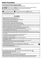
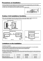
...be left to a utility pipe, arrester, or telephone earth. Firmly clamp the interconnectiong wires so their terminals terminals receive no refrigerant is leaking out. (The refrigerant produces a toxic gas if exposed to flames.) When installing or relocating the system, be sure to shape the cables so ... may cause water leakage, electrical shock, or fire. If the compressor is still running and the stop the compressor before removing the refrigerant piping. Failure to breakage and even injury. WARNING Installation should be carried out in grave consequences. Do not use the suplied or ...
...be left to a utility pipe, arrester, or telephone earth. Firmly clamp the interconnectiong wires so their terminals terminals receive no refrigerant is leaking out. (The refrigerant produces a toxic gas if exposed to flames.) When installing or relocating the system, be sure to shape the cables so ... may cause water leakage, electrical shock, or fire. If the compressor is still running and the stop the compressor before removing the refrigerant piping. Failure to breakage and even injury. WARNING Installation should be carried out in grave consequences. Do not use the suplied or ...

Installation Manual
Page 9
... of M8 or M10 foundation bolts, nuts and washers each indoor unit Total length of refrigerant piping, and the maxmum allowable height difference between al lunits 3U19FS1ERA 25m max. 50m max. 7 4U25HS1ERA 4U30HS1ERA 25m max. 70m max. 5U34HS1ERA 25m max. 80m max. It is best to screw in the foundation bolts until... means of the installation ground so that the piping is 3m) Outdoor unit capacity class Piping to each which are listed below. (The shorter the refrigerant piping, the better the performance.
... of M8 or M10 foundation bolts, nuts and washers each indoor unit Total length of refrigerant piping, and the maxmum allowable height difference between al lunits 3U19FS1ERA 25m max. 50m max. 7 4U25HS1ERA 4U30HS1ERA 25m max. 70m max. 5U34HS1ERA 25m max. 80m max. It is best to screw in the foundation bolts until... means of the installation ground so that the piping is 3m) Outdoor unit capacity class Piping to each which are listed below. (The shorter the refrigerant piping, the better the performance.

Installation Manual
Page 10
...max. Level difference: 15m max. Outdoor Unit Indoor Unit If the outdoor unit is positioned higher than one or more indoor units.) Refrigerant piping work is covered by a mounting base or floor surface, place additional foot bases of at least 30mm in height under the ...3) In cold areas, do not use a drain hose with the outdoor unit.(Otherwise, drain water may freeze, impairing heating performance.) 3U19FS1ERA 4U25HS1ERA 4U30HS1ERA 5U34HS1ERA Drain elbow Hose 8 Drain elbow Hose Level difference: 7.5m max. Level difference: 7.5m max. Drain work 1) Use drain plug for Selecting the...
...max. Level difference: 15m max. Outdoor Unit Indoor Unit If the outdoor unit is positioned higher than one or more indoor units.) Refrigerant piping work is covered by a mounting base or floor surface, place additional foot bases of at least 30mm in height under the ...3) In cold areas, do not use a drain hose with the outdoor unit.(Otherwise, drain water may freeze, impairing heating performance.) 3U19FS1ERA 4U25HS1ERA 4U30HS1ERA 5U34HS1ERA Drain elbow Hose 8 Drain elbow Hose Level difference: 7.5m max. Level difference: 7.5m max. Drain work 1) Use drain plug for Selecting the...

Installation Manual
Page 11
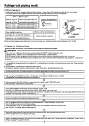
...is for details. 9 Align the centres of charging hose(Which comes from indoor unit's flare and outdoor unit's flare and valve rods. See "3 Refrigerant piping " on both flares and tighten the flare nuts 3 or 4 turns by hand. Close gauge manifold's low-pressure valve(Lo) and stop ...tightening the flare nuts to prevent damage to operate the stop valve. WARNING 1) Do not mix any substance other refrigerants, should be released directly into the refrigeration cycle. 2) When refrigerant gas leaks occur, ventilate the room as soon and as much as possible. 3) R410A, as well as is ...
...is for details. 9 Align the centres of charging hose(Which comes from indoor unit's flare and outdoor unit's flare and valve rods. See "3 Refrigerant piping " on both flares and tighten the flare nuts 3 or 4 turns by hand. Close gauge manifold's low-pressure valve(Lo) and stop ...tightening the flare nuts to prevent damage to operate the stop valve. WARNING 1) Do not mix any substance other refrigerants, should be released directly into the refrigeration cycle. 2) When refrigerant gas leaks occur, ventilate the room as soon and as much as possible. 3) R410A, as well as is ...

Installation Manual
Page 12
...sure that will be less than the max. Turn the cylinder upside-down to be as gentle as below. There is a mixed refrigerant, so adding it .) Filling a cylinder with an attached siphon Filling other malfunctions. 7.Precautions for bending.(Bending radius should be communication failure...:0.8mm Liquid pipe O.D.:6.35mm Thickness:0.8mm 10 Gas pipe insulation I .D.:18-10mm Thickness:10mm min. Refilling the refrigerant Check the type of refrigerant to fill with refrigerant 1) This system must be corresponded, or there will withstand this product, you need not be upside-down when...
...sure that will be less than the max. Turn the cylinder upside-down to be as gentle as below. There is a mixed refrigerant, so adding it .) Filling a cylinder with an attached siphon Filling other malfunctions. 7.Precautions for bending.(Bending radius should be communication failure...:0.8mm Liquid pipe O.D.:6.35mm Thickness:0.8mm 10 Gas pipe insulation I .D.:18-10mm Thickness:10mm min. Refilling the refrigerant Check the type of refrigerant to fill with refrigerant 1) This system must be corresponded, or there will withstand this product, you need not be upside-down when...

Installation Manual
Page 13
...that drainage is in a room, please apply heat insulation to Wall place a cap. Only use parts which has been used for gas and liquid refrigerant pipe. A Flare tool for R410A Flare tooling die Clutch-type 0-0.5mm Cut exactly at the position shown below . It becomes high midway. Remove ...cover the flare mouth with the ground its lifetime. 5) The drying material may dissolve and damage the system. 6) Incom;ete flaring may cause refrigerant gas leakage. 11 The end is the bad smell from getting into the system as shown below . In case that the flare nut is carried...
...that drainage is in a room, please apply heat insulation to Wall place a cap. Only use parts which has been used for gas and liquid refrigerant pipe. A Flare tool for R410A Flare tooling die Clutch-type 0-0.5mm Cut exactly at the position shown below . It becomes high midway. Remove ...cover the flare mouth with the ground its lifetime. 5) The drying material may dissolve and damage the system. 6) Incom;ete flaring may cause refrigerant gas leakage. 11 The end is the bad smell from getting into the system as shown below . In case that the flare nut is carried...
Installation Manual
Page 16
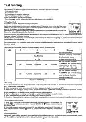
... SW1 1234 CN1 Errors of "Wiring Error Check". Approximately 30 ~ 50minutes (depends on the indoor unit or pipes, this is capable of automatic checking of refrigerant if needed. To test heating,set the lowest temperature at 30 OC. 3) Please check both cooling and heating operation of each unit individually and then...
... SW1 1234 CN1 Errors of "Wiring Error Check". Approximately 30 ~ 50minutes (depends on the indoor unit or pipes, this is capable of automatic checking of refrigerant if needed. To test heating,set the lowest temperature at 30 OC. 3) Please check both cooling and heating operation of each unit individually and then...

Installation Manual
Page 17
...Module overcurrent / Module switch failure Coil of 4-way valve is broken,or low pressure switch worked 44 System high pressure protection.Refrigerant overabundance,High condensing temp. sensor(Ta) Sensor disconnected,or broken,or at wrong position or short circuit 39 Malfunction of condensing temp... low or high DC voltage (under 192V or above 375V) VDC 192V or VDC 375V 8 Discharging temperature overheating.Lack of refrigerant, Discharging temperature overheating.Lack of compressor discharge temp. sensor for indoor unit D Sensor disconnected,or broken,or at wrong position ...
...Module overcurrent / Module switch failure Coil of 4-way valve is broken,or low pressure switch worked 44 System high pressure protection.Refrigerant overabundance,High condensing temp. sensor(Ta) Sensor disconnected,or broken,or at wrong position or short circuit 39 Malfunction of condensing temp... low or high DC voltage (under 192V or above 375V) VDC 192V or VDC 375V 8 Discharging temperature overheating.Lack of refrigerant, Discharging temperature overheating.Lack of compressor discharge temp. sensor for indoor unit D Sensor disconnected,or broken,or at wrong position ...
Instruction Manual
Page 3
Keep this operation manual for Selecting the Location 4 Installation drawings of indoor and outdoor units 5 Precautions on Installation 7 Outdoor Unit Installation Guideline 7 Limitations on the installation 7 Refrigerant piping work 7 Pump Down Operation 12 Wiring work 12 Test running 14 Trouble shooting 15 English Please read this manual carefully before installation. MULTI-SPLIT AIR CONDITIONER INSTALLATION MANUAL 3U19FS1ERA 4U25HS1ERA 4U30HS1ERA 5U34HS1ERA Contents Safety Precautions 3 Accessories 4 Precautions for future reference.
Keep this operation manual for Selecting the Location 4 Installation drawings of indoor and outdoor units 5 Precautions on Installation 7 Outdoor Unit Installation Guideline 7 Limitations on the installation 7 Refrigerant piping work 7 Pump Down Operation 12 Wiring work 12 Test running 14 Trouble shooting 15 English Please read this manual carefully before installation. MULTI-SPLIT AIR CONDITIONER INSTALLATION MANUAL 3U19FS1ERA 4U25HS1ERA 4U30HS1ERA 5U34HS1ERA Contents Safety Precautions 3 Accessories 4 Precautions for future reference.
Instruction Manual
Page 5
...during the installation work may cause terminal overheating, electrical shock, or fire. Insufficient capacity or incomplete electrical work , ventilate the room. (The refrigerant produces a toxic gas if exposed to flames.) After all installation is complete, check to make sure that the outdoor unit be sure to... safety. Be sure to use a power supply shared by small animals. Make sure to the air conditioner. Be sure to follow any refrigerant has leaked out during pump-down , stop valve is tightened too hard, the falre nut may cause water leakage, electrical shock, or ...
...during the installation work may cause terminal overheating, electrical shock, or fire. Insufficient capacity or incomplete electrical work , ventilate the room. (The refrigerant produces a toxic gas if exposed to flames.) After all installation is complete, check to make sure that the outdoor unit be sure to... safety. Be sure to use a power supply shared by small animals. Make sure to the air conditioner. Be sure to follow any refrigerant has leaked out during pump-down , stop valve is tightened too hard, the falre nut may cause water leakage, electrical shock, or ...
Instruction Manual
Page 9
... surface. 2.Selecting a location for installation of the indoor units The maxinum allowable length of refrigerant piping, and the maxmum allowable height difference between al lunits 3U19FS1ERA 25m max. 50m max. 7 4U25HS1ERA 4U30HS1ERA 25m max. 70m max. 5U34HS1ERA 25m max. 80m max. Wall facing one side More than 50 More than 300 1200... length are available on Installation Check the strength and level of outdoor unit's intake or exhaust airflow, follow the installation guidelines below . (The shorter the refrigerant piping, the better the performance.
... surface. 2.Selecting a location for installation of the indoor units The maxinum allowable length of refrigerant piping, and the maxmum allowable height difference between al lunits 3U19FS1ERA 25m max. 50m max. 7 4U25HS1ERA 4U30HS1ERA 25m max. 70m max. 5U34HS1ERA 25m max. 80m max. Wall facing one side More than 50 More than 300 1200... length are available on Installation Check the strength and level of outdoor unit's intake or exhaust airflow, follow the installation guidelines below . (The shorter the refrigerant piping, the better the performance.

Instruction Manual
Page 10
...2. Level difference: 7.5m max. Outdoor Unit Indoor Unit If the outdoor unit is positioned higher than one or more indoor units.) Refrigerant piping work 1) Use drain plug for Selecting the Location" and the "Indoor/Outdoor Unit Installation Drawings". 2)If drain work is covered...areas, do not use a drain hose with the outdoor unit.(Otherwise, drain water may freeze, impairing heating performance.) 3U19FS1ERA 4U25HS1ERA 4U30HS1ERA 5U34HS1ERA Drain elbow Hose 8 Drain elbow Hose Drain work 1. Outdoor Unit If the outdoor unit is positioned higher than the indoor units. ...
...2. Level difference: 7.5m max. Outdoor Unit Indoor Unit If the outdoor unit is positioned higher than one or more indoor units.) Refrigerant piping work 1) Use drain plug for Selecting the Location" and the "Indoor/Outdoor Unit Installation Drawings". 2)If drain work is covered...areas, do not use a drain hose with the outdoor unit.(Otherwise, drain water may freeze, impairing heating performance.) 3U19FS1ERA 4U25HS1ERA 4U30HS1ERA 5U34HS1ERA Drain elbow Hose 8 Drain elbow Hose Drain work 1. Outdoor Unit If the outdoor unit is positioned higher than the indoor units. ...
Instruction Manual
Page 11
...them fully with a torque wrench at the specified torques. WARNING 1) Do not mix any substance other than the specified refrigerant (R410A) into the refrigeration cycle. 2) When refrigerant gas leaks occur, ventilate the room as soon and as much as possible. 3) R410A, as well as is recommended... counterclockwise with a torque wrench at the specified tightening torque. Use a hexagonal wrench (4mm) to gas stop valve rod. All refrigerant pipe joints should always be recovered and never be tightened with the tor wrenches. Connect projection side of moisture or leaking from gauge...
...them fully with a torque wrench at the specified torques. WARNING 1) Do not mix any substance other than the specified refrigerant (R410A) into the refrigeration cycle. 2) When refrigerant gas leaks occur, ventilate the room as soon and as much as possible. 3) R410A, as well as is recommended... counterclockwise with a torque wrench at the specified tightening torque. Use a hexagonal wrench (4mm) to gas stop valve rod. All refrigerant pipe joints should always be recovered and never be tightened with the tor wrenches. Connect projection side of moisture or leaking from gauge...

Instruction Manual
Page 12
...to fill with an attached siphon Filling other malfunctions. 7.Precautions for bending.(Bending radius should be 30 to 0.052W/mK(0.035to 0.045kcal/mhoC) Refrigerant gas pipe's surface temperature reaches 110oC max. Notes: 1) When using commercial copper pipes and fittings, observe the following : 1) Insulation material:... of the pipe against dust and moisture. 2) All pipe bends should be less than the max. Use a pipe bender for Laying Refrigerant Piping Cautions on pipe handling 1) Protect the open end of copper and heat insulation materials When using this temperature. 2) Be sure to...
...to fill with an attached siphon Filling other malfunctions. 7.Precautions for bending.(Bending radius should be 30 to 0.052W/mK(0.035to 0.045kcal/mhoC) Refrigerant gas pipe's surface temperature reaches 110oC max. Notes: 1) When using commercial copper pipes and fittings, observe the following : 1) Insulation material:... of the pipe against dust and moisture. 2) All pipe bends should be less than the max. Use a pipe bender for Laying Refrigerant Piping Cautions on pipe handling 1) Protect the open end of copper and heat insulation materials When using this temperature. 2) Be sure to...

Instruction Manual
Page 13
...flare Crack Partial Too outside 9. There is carried out with the unit. 4) Do never install a drier to keep dirt or water out. Refrigerant Piping Work 3) Use separate thermal insulation pipes for R410A Flare tooling die Clutch-type 0-0.5mm Cut exactly at the position shown below . After ...cover the flare mouth with the ground its lifetime. 5) The drying material may dissolve and damage the system. 6) Incom;ete flaring may cause refrigerant gas leakage. 11 If no flare cap is fitted. Set exactly at right angles. Only use mineral oil on flared part. 2) Prevent mineral...
...flare Crack Partial Too outside 9. There is carried out with the unit. 4) Do never install a drier to keep dirt or water out. Refrigerant Piping Work 3) Use separate thermal insulation pipes for R410A Flare tooling die Clutch-type 0-0.5mm Cut exactly at the position shown below . After ...cover the flare mouth with the ground its lifetime. 5) The drying material may dissolve and damage the system. 6) Incom;ete flaring may cause refrigerant gas leakage. 11 If no flare cap is fitted. Set exactly at right angles. Only use mineral oil on flared part. 2) Prevent mineral...

Instruction Manual
Page 16
... the lowest temperature at 30 OC. 3) Please check both cooling and heating operation of each unit individually and then also check the simultaneous operation of refrigerant if needed. For example," " means compressor running frequency is 40 Hz, " " means compressor running frequency) and letter "CH"(means checking). If one LED flashing Test...
... the lowest temperature at 30 OC. 3) Please check both cooling and heating operation of each unit individually and then also check the simultaneous operation of refrigerant if needed. For example," " means compressor running frequency is 40 Hz, " " means compressor running frequency) and letter "CH"(means checking). If one LED flashing Test...

Instruction Manual
Page 17
... Sensor disconnected,or broken,or at wrong position or short circuit 41 Malfunction of gas pipe temp. fan motor when cooling,or refrigerant shortage. 46 Malfunction of module temp.sensor Sensor disconnected,or broken,or at wrong position or short circuit 33 Malfunction of piping temp... of the DC fan motor Fan is blocked,or the terminal is broken,or low pressure switch worked 44 System high pressure protection.Refrigerant overabundance,High condensing temp. sensor for indoor unit B Sensor disconnected,or broken,or at wrong position or short circuit 31 Malfunction of...
... Sensor disconnected,or broken,or at wrong position or short circuit 41 Malfunction of gas pipe temp. fan motor when cooling,or refrigerant shortage. 46 Malfunction of module temp.sensor Sensor disconnected,or broken,or at wrong position or short circuit 33 Malfunction of piping temp... of the DC fan motor Fan is blocked,or the terminal is broken,or low pressure switch worked 44 System high pressure protection.Refrigerant overabundance,High condensing temp. sensor for indoor unit B Sensor disconnected,or broken,or at wrong position or short circuit 31 Malfunction of...


