Service Manual
Page 1
21F8D-S COLOUR TELEVISION Service Manual Haier Haier Features 54cm super flat picture tube Auto search 218 programs presetting and memory Child Lock & On Screen Help Function Haier group
21F8D-S COLOUR TELEVISION Service Manual Haier Haier Features 54cm super flat picture tube Auto search 218 programs presetting and memory Child Lock & On Screen Help Function Haier group
Service Manual
Page 2
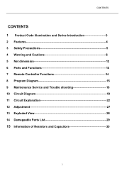
CONTENTS CONTENTS 1 Product Code illumination and Series Introduction 3 2 Features 4 3 Safety Precautions 5 4 Warning and Cautions 6 5 Net dimension 12 6 Parts and Functions 13 7 Remote Controller Functions 14 8 Program Diagram 15 9 Maintenance Service and Trouble shooting 18 10 Circuit Diagram 19 11 Circuit Explanation 22 12 Adjustment 27 13 Exploded View 28 14 Damageable Parts List 29 15 Information of Resistors and Capacitors 30 2
CONTENTS CONTENTS 1 Product Code illumination and Series Introduction 3 2 Features 4 3 Safety Precautions 5 4 Warning and Cautions 6 5 Net dimension 12 6 Parts and Functions 13 7 Remote Controller Functions 14 8 Program Diagram 15 9 Maintenance Service and Trouble shooting 18 10 Circuit Diagram 19 11 Circuit Explanation 22 12 Adjustment 27 13 Exploded View 28 14 Damageable Parts List 29 15 Information of Resistors and Capacitors 30 2

Service Manual
Page 3
Product Code illumination and Series Introduction 21 F 8D - S Company of Signal processor IC TD:Toshibe Color television appearance pure flat CRT size(unit:inch) 3 Product Code illumination and Series Introduction 1.
Product Code illumination and Series Introduction 21 F 8D - S Company of Signal processor IC TD:Toshibe Color television appearance pure flat CRT size(unit:inch) 3 Product Code illumination and Series Introduction 1.
Service Manual
Page 4
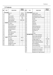
... Multi-audio modes 15 Tone adjuster 16 MTS/SAP 17 Auto-volume leveling 18 JACK AV input 19 AV output 20 DVD terminal 21 S-video jack 22 Headphone socket 23 SCART socket Functions MODEL 21F8D-s NO. ITEM FUNCTION MODEL 21F8D-s 76818 Pure flat PAL NTSC B/G 218 ENGLISH back 1 √ back 1 √ × × 24 SOFTWARE Digital curtain √ 25 Slow fading on & off √ 26 Semitransparent menu √ 27 Non-flshing channel changing ×...
... Multi-audio modes 15 Tone adjuster 16 MTS/SAP 17 Auto-volume leveling 18 JACK AV input 19 AV output 20 DVD terminal 21 S-video jack 22 Headphone socket 23 SCART socket Functions MODEL 21F8D-s NO. ITEM FUNCTION MODEL 21F8D-s 76818 Pure flat PAL NTSC B/G 218 ENGLISH back 1 √ back 1 √ × × 24 SOFTWARE Digital curtain √ 25 Slow fading on & off √ 26 Semitransparent menu √ 27 Non-flshing channel changing ×...
Service Manual
Page 5
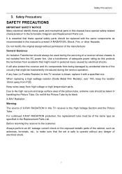
...Schematic Diagram and Replacement Parts List. When replacing a high wattage resistor (Oxide Metal Film Resistor, over 1W), keep the resistor 10mm away from high voltage or high temperature parts. It is essential that these parts and mechanical parts in personal injury caused by its Neck. Do not lift the Picture... without any fuse (or Fusible Resistor) in this manual to make sure that might result in this TV receiver is blown, replace it 's components from being damaged by accidental shorts of the same type as antennas, terminals, etc., to prevent X-RADIATION, Shock, Fire...
...Schematic Diagram and Replacement Parts List. When replacing a high wattage resistor (Oxide Metal Film Resistor, over 1W), keep the resistor 10mm away from high voltage or high temperature parts. It is essential that these parts and mechanical parts in personal injury caused by its Neck. Do not lift the Picture... without any fuse (or Fusible Resistor) in this manual to make sure that might result in this TV receiver is blown, replace it 's components from being damaged by accidental shorts of the same type as antennas, terminals, etc., to prevent X-RADIATION, Shock, Fire...
Service Manual
Page 6
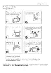
...components in thunder and lightening, please pull out the plug from AC outlet and the antenna plug from the cover of the TV set and harm you clean the TV set, please pull out the power plug from firing and electric shock, don't make the TV set from AC outlet. If using life of the TV set...clean the cabinet and the screen with a dry cotton cloth after cutting off the power.Don't use any cleanser. To prevent the TV set rain or moisture. 2. ...needed to prolong the using hard cloth, the tube surface will be used for long time or it is in the TV set , please place it on the display...
...components in thunder and lightening, please pull out the plug from AC outlet and the antenna plug from the cover of the TV set and harm you clean the TV set, please pull out the power plug from firing and electric shock, don't make the TV set from AC outlet. If using life of the TV set...clean the cabinet and the screen with a dry cotton cloth after cutting off the power.Don't use any cleanser. To prevent the TV set rain or moisture. 2. ...needed to prolong the using hard cloth, the tube surface will be used for long time or it is in the TV set , please place it on the display...
Service Manual
Page 7
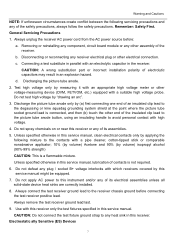
... clip lead to the picture tube anode button, using an insulating handle to avoid personal contact with high voltage. 4. Unless specified otherwise in this service manual, lubrication of the receiver. Do not apply AC power to the receiver chassis ground before : a. Removing or reinstalling any component, circuit board module or any of its assemblies. 5. Always connect the test receiver...
... clip lead to the picture tube anode button, using an insulating handle to avoid personal contact with high voltage. 4. Unless specified otherwise in this service manual, lubrication of the receiver. Do not apply AC power to the receiver chassis ground before : a. Removing or reinstalling any component, circuit board module or any of its assemblies. 5. Always connect the test receiver...

Service Manual
Page 8
... install it. (Most replacement ES devices are integrated circuits and some normally harmless motions such as "anti-static" can generate electrical charges sufficient to the chassis or circuit assembly into which should be removed to prevent potential shock prior to applying power to help reduce the incidence of 60 parts tin/40 parts lead. 3. Use a mall wire bristle (0.5 inch...
... install it. (Most replacement ES devices are integrated circuits and some normally harmless motions such as "anti-static" can generate electrical charges sufficient to the chassis or circuit assembly into which should be removed to prevent potential shock prior to applying power to help reduce the incidence of 60 parts tin/40 parts lead. 3. Use a mall wire bristle (0.5 inch...

Service Manual
Page 9
... lead against the circuit foil. CAUTION: Work quickly to 600o F) b. Use the following technique should be used to metal contact then solder each IC lead in the circuit board. When holes are inserted and then bent flat against the circuit foil pad and solder... the component lead and the foil. Bend into a "U" shape the replacement transistor leads. Quickly draw the melted solder with an anti-static, suction-type solder removal device with a small wire-bristle brush. Replacement Carefully insert the replacement IC in one operation by clipping its leads as close as ...
... lead against the circuit foil. CAUTION: Work quickly to 600o F) b. Use the following technique should be used to metal contact then solder each IC lead in the circuit board. When holes are inserted and then bent flat against the circuit foil pad and solder... the component lead and the foil. Bend into a "U" shape the replacement transistor leads. Quickly draw the melted solder with an anti-static, suction-type solder removal device with a small wire-bristle brush. Replacement Carefully insert the replacement IC in one operation by clipping its leads as close as ...

Service Manual
Page 10
... to prevent excessive component temperatures. If they are not shiny, reheat them and if necessary, apply additional solder. Carefully scratch away the solder resist and acrylic coating (if used) from the heat sink of the circuit board. Remove the heat sink mounting screw (if so equipped). Warning and Cautions Power Output, Transistor Device Removal/Replacement Heat and remove all solder...
... to prevent excessive component temperatures. If they are not shiny, reheat them and if necessary, apply additional solder. Carefully scratch away the solder resist and acrylic coating (if used) from the heat sink of the circuit board. Remove the heat sink mounting screw (if so equipped). Warning and Cautions Power Output, Transistor Device Removal/Replacement Heat and remove all solder...

Service Manual
Page 11
... the installation of a jumper wire on the other connections Use the following technique to repair the defective copper pattern at least 1/4 inch of copper, to insure that it around the IC pin. Route the jumper wire along the copper pattern from the lead of the nearest component on...jumper wire is directly connected to the lead of the nearest component on the component side of the pattern break and locate the nearest component that is dressed so that a hazardous condition will not exist if the jumper wire opens. 2. Net dimension Net dimension 11 Connect insulated 20-gauge ...
... the installation of a jumper wire on the other connections Use the following technique to repair the defective copper pattern at least 1/4 inch of copper, to insure that it around the IC pin. Route the jumper wire along the copper pattern from the lead of the nearest component on...jumper wire is directly connected to the lead of the nearest component on the component side of the pattern break and locate the nearest component that is dressed so that a hazardous condition will not exist if the jumper wire opens. 2. Net dimension Net dimension 11 Connect insulated 20-gauge ...
Service Manual
Page 14
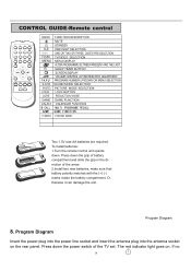
... red indicator light goes on the rear panel. Program Diagram 8. CONTROL GUIDE-Remote control + + Two 1.5V size AA batteries are required. If no 14 Press down the grip of battery compartment and slide the grip in the direction of the TV set. Program Diagram Insert the power plug into the power line socket and insert the antenna plug into the antenna socket on . To install batteries: 1.Turn the remote control unit upside down the power switch of...
... red indicator light goes on the rear panel. Program Diagram 8. CONTROL GUIDE-Remote control + + Two 1.5V size AA batteries are required. If no 14 Press down the grip of battery compartment and slide the grip in the direction of the TV set. Program Diagram Insert the power plug into the power line socket and insert the antenna plug into the antenna socket on . To install batteries: 1.Turn the remote control unit upside down the power switch of...
Service Manual
Page 15
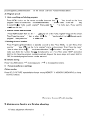
... channel number Press Program up the "tune program" menu on the remote controller. Maintenance Service and Trouble shooting 9. If you do not want to ON. Press MENU to call up /down buttons to select a channel to chang the Picture Mode. Enter the number that you want to see .Then Then select "SKIP" and select SKIP to stop ,press the key " ". 2. Maintenance Service and Trouble shooting 1.Factory adjustment information 15 Follow the steps below. B Volume...
... channel number Press Program up the "tune program" menu on the remote controller. Maintenance Service and Trouble shooting 9. If you do not want to ON. Press MENU to call up /down buttons to select a channel to chang the Picture Mode. Enter the number that you want to see .Then Then select "SKIP" and select SKIP to stop ,press the key " ". 2. Maintenance Service and Trouble shooting 1.Factory adjustment information 15 Follow the steps below. B Volume...
Service Manual
Page 16
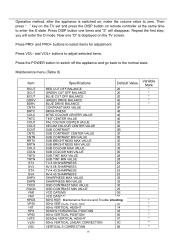
Now one times and "S" will disappear, Repeat the first step, you will enter the D mode. and VOL+ buttons to adjust selected items. Press the POWER button to switch off the appliance and go back to enter the S state. Press DISP button one "D" is switched on, make the volume value to select items for adjustment. Press VOL- Maintenance menu (Table 8) Item RCUT GCUT BCUT GDRV BDRV...
Now one times and "S" will disappear, Repeat the first step, you will enter the D mode. and VOL+ buttons to adjust selected items. Press the POWER button to switch off the appliance and go back to enter the S state. Press DISP button one "D" is switched on, make the volume value to select items for adjustment. Press VOL- Maintenance menu (Table 8) Item RCUT GCUT BCUT GDRV BDRV...
Service Manual
Page 22
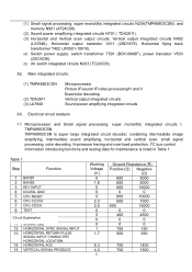
... (3) LA7840 Microprocessor Picture IF/sound IF/video processing/H and V Scan/color decoding Vertical output integrated circuits Sound power amplifying integrated circuits A3. Table 1 Step Function 1 BAND1 2 BAND2 3 KEY INPUT 4 DIGITAL GND 5 CPU RESET 6 CPU CLOCK 7 CPU ClOCK 8 TEST 9 +5 VCC C1ir0cuit EGxNpDlanation 11 SIGNAL GND 12 HORIZONTAL SYNC SIGNAL INPUT 13 HORIZONTAL RETURN PULSE SIGNAL INPUT CHARACTER HORIZONTAL LOCATION 14 HORIZONTAL AGC 15 VERTICAL SIGNAL PRODUCE Working Voltage (V) 0 1.8 5 0 5 2.3 2.0 0 5 0 0 1 1.7 Ground...
... (3) LA7840 Microprocessor Picture IF/sound IF/video processing/H and V Scan/color decoding Vertical output integrated circuits Sound power amplifying integrated circuits A3. Table 1 Step Function 1 BAND1 2 BAND2 3 KEY INPUT 4 DIGITAL GND 5 CPU RESET 6 CPU CLOCK 7 CPU ClOCK 8 TEST 9 +5 VCC C1ir0cuit EGxNpDlanation 11 SIGNAL GND 12 HORIZONTAL SYNC SIGNAL INPUT 13 HORIZONTAL RETURN PULSE SIGNAL INPUT CHARACTER HORIZONTAL LOCATION 14 HORIZONTAL AGC 15 VERTICAL SIGNAL PRODUCE Working Voltage (V) 0 1.8 5 0 5 2.3 2.0 0 5 0 0 1 1.7 Ground...
Service Manual
Page 24
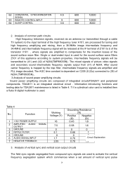
... of sound power amplifying circuits Sound power amplifying circuits are used . Single or dual-ended input is dependent on C205 (0.22u) connected to (41) and (42) of integrated circuitsTDA2611 and peripheral components. The mixed signals of picture video signals and secondary sound intermediate frequency signals output from compound sync signals are composed of N204(TMP8803SN). Table 4 No. Function Working Voltage (V) 1 +16V POWER SUPPLY 2 AMPLIFIED AUDIO SIGNAL OUTPUT 3 GROUND 4 RIPPLE FILTER 5 GROUND 6 AUDIO SIGNAL INPUT 7 NEGATIVE...
... of sound power amplifying circuits Sound power amplifying circuits are used . Single or dual-ended input is dependent on C205 (0.22u) connected to (41) and (42) of integrated circuitsTDA2611 and peripheral components. The mixed signals of picture video signals and secondary sound intermediate frequency signals output from compound sync signals are composed of N204(TMP8803SN). Table 4 No. Function Working Voltage (V) 1 +16V POWER SUPPLY 2 AMPLIFIED AUDIO SIGNAL OUTPUT 3 GROUND 4 RIPPLE FILTER 5 GROUND 6 AUDIO SIGNAL INPUT 7 NEGATIVE...

Service Manual
Page 25
... horizontal scan output circuits As the horizontal oscillation circuit is listed in Table 4. if a cylindrical color card is installed then a fluke III digital multimeter is output from (16) of N402. The horizontal return pulse output from (8) of T402 is transmitted from pin (2) of N204 (TMP8803SN) to N204 (13) are phase-lock loop filters. The external capacitor C244 (0.1uF) of switching mode power circuits...
... horizontal scan output circuits As the horizontal oscillation circuit is listed in Table 4. if a cylindrical color card is installed then a fluke III digital multimeter is output from (16) of N402. The horizontal return pulse output from (8) of T402 is transmitted from pin (2) of N204 (TMP8803SN) to N204 (13) are phase-lock loop filters. The external capacitor C244 (0.1uF) of switching mode power circuits...

Service Manual
Page 26
The adjustment points are transmitted to V501 to control the switch velocity and hold the output voltage normal. V503, Primary coil 3-7 and feedback coil 1-2 form a self-actuated oscillator. The current passed V512 is larger and the operating time of the switching mode transformer T501, rectified and filtered by VD556 and C563 is +110V direct current voltage which is supplied. The coupler...
The adjustment points are transmitted to V501 to control the switch velocity and hold the output voltage normal. V503, Primary coil 3-7 and feedback coil 1-2 form a self-actuated oscillator. The current passed V512 is larger and the operating time of the switching mode transformer T501, rectified and filtered by VD556 and C563 is +110V direct current voltage which is supplied. The coupler...
Service Manual
Page 27
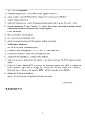
.... 2. White balance adjustment. 1) Set the picture mode on the power and connect the signals to the tuner to the tuner. 2) Adjust variable resistor RP501 until the voltage of the screen menu. 13. Hold the horizontal size is 90-92%. 8. 1. +B: 115±0.3V adjustment. 1) Switch on standard mode. 3) Adjust focus potentiometer until the optimum picture is achieved. 4. Focus adjustment. 1) Receive electronic circular signal. 2) Set picture mode on the power and connect PAL circular signals to receive PAL...
.... 2. White balance adjustment. 1) Set the picture mode on the power and connect the signals to the tuner to the tuner. 2) Adjust variable resistor RP501 until the voltage of the screen menu. 13. Hold the horizontal size is 90-92%. 8. 1. +B: 115±0.3V adjustment. 1) Switch on standard mode. 3) Adjust focus potentiometer until the optimum picture is achieved. 4. Focus adjustment. 1) Receive electronic circular signal. 2) Set picture mode on the power and connect PAL circular signals to receive PAL...

Service Manual
Page 29
Damageable Parts List 14. Damageable Parts List MATERIAL CODE LOCATION NOME OF THE PART TYPE RReaptea(r%tio)nUNIT PRICE($) Remar 0094101395 R550 FUSE RESISTOR RF10-1/2W-2.2-J-15-C-A 0.003 0.01140276 0094102214 R558... FBT JF0501-19910 0.001 4.476639225 0094002267 REMOTE CONTROLLER HTR-020 0.003 1.799102179 0094001709 SW501 POWER SWITCH KDC-A06C-2 0.003 0.422324455 0090400764 POWER CABLE TJC1-2Y 0.006 0.001234867 0094500865 T501 POWER TRANSFORMER BCK-08A6F 0.001 1.119159806 0094001445 A101 ELECTRICAL TUNER ENV59D69F1E 0.003 4.339383777 0094300060 XZ601 TUBE ...
Damageable Parts List 14. Damageable Parts List MATERIAL CODE LOCATION NOME OF THE PART TYPE RReaptea(r%tio)nUNIT PRICE($) Remar 0094101395 R550 FUSE RESISTOR RF10-1/2W-2.2-J-15-C-A 0.003 0.01140276 0094102214 R558... FBT JF0501-19910 0.001 4.476639225 0094002267 REMOTE CONTROLLER HTR-020 0.003 1.799102179 0094001709 SW501 POWER SWITCH KDC-A06C-2 0.003 0.422324455 0090400764 POWER CABLE TJC1-2Y 0.006 0.001234867 0094500865 T501 POWER TRANSFORMER BCK-08A6F 0.001 1.119159806 0094001445 A101 ELECTRICAL TUNER ENV59D69F1E 0.003 4.339383777 0094300060 XZ601 TUBE ...


