Operation Manual
Page 1
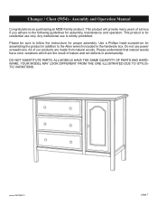
...Manual Congratulations on purchasing an MDB Family product. ALL MODELS HAVE THE SAME QUANTITY OF PARTS AND HARDWARE. YOUR MODEL... MAY LOOK DIFFERENT FROM THE ONE ILLUSTRATED DUE TO STYLISTIC VARIATIONS. This product will provide many years of our products are the result of nature and not defects in the hardware box. Please be sure to follow the instructions.... DO NOT SUBSTITUTE PARTS. Changer / Chest (5954) - This product is strictly prohibited. Any institutional use power screwdrivers. All of service if you adhere to...
...Manual Congratulations on purchasing an MDB Family product. ALL MODELS HAVE THE SAME QUANTITY OF PARTS AND HARDWARE. YOUR MODEL... MAY LOOK DIFFERENT FROM THE ONE ILLUSTRATED DUE TO STYLISTIC VARIATIONS. This product will provide many years of our products are the result of nature and not defects in the hardware box. Please be sure to follow the instructions.... DO NOT SUBSTITUTE PARTS. Changer / Chest (5954) - This product is strictly prohibited. Any institutional use power screwdrivers. All of service if you adhere to...
Operation Manual
Page 2
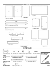
PARTS HARDWARE Tools Needed (not included) Phillips screwdriver page 2
PARTS HARDWARE Tools Needed (not included) Phillips screwdriver page 2
Operation Manual
Page 3
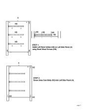
STEP 1: Install Left Panel Glides (H9) on Left Side Panel (A) using Small Wood Screws (H6) STEP 2: Screw three Cam Bolts (H2) into Left Side Panel (A) page 3
STEP 1: Install Left Panel Glides (H9) on Left Side Panel (A) using Small Wood Screws (H6) STEP 2: Screw three Cam Bolts (H2) into Left Side Panel (A) page 3
Operation Manual
Page 4
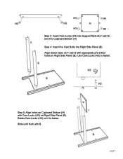
H3 H3 H H3 H3 Step 3: Insert Cam Locks (H3) into Support Rails (E,F and G) and into Cupboard Bottom (H) Step 4: Insert five Cam Bolts into Right Side Panel (B) Align dowel holes on F and G with appropriate pre-drilled holes on Right Side Panel (B). Slide until flush with Cam Locks (H3) on Right Side Panel (B). Step 5: Align holes on Cupboard Bottom (H) with B. Rotate Cam Locks (H3) on H to fasten. page 4 Use Cam Locks (H3) to fasten.
H3 H3 H H3 H3 Step 3: Insert Cam Locks (H3) into Support Rails (E,F and G) and into Cupboard Bottom (H) Step 4: Insert five Cam Bolts into Right Side Panel (B) Align dowel holes on F and G with appropriate pre-drilled holes on Right Side Panel (B). Slide until flush with Cam Locks (H3) on Right Side Panel (B). Step 5: Align holes on Cupboard Bottom (H) with B. Rotate Cam Locks (H3) on H to fasten. page 4 Use Cam Locks (H3) to fasten.
Operation Manual
Page 5
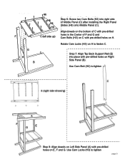
... (H3) to fasten C. H6 H6 H6 H8 Step 6: Screw two Cam Bolts (H2) into place with pre-drilled holes on E, F and G. G H B Step 7: Align Top Back Support Rail (E) into right side of F and G and Cam Bolts (H2) on C with pre-drilled holes on H. Rotate Cam Locks (H3) on the bottom of C with... pre-drilled F C (left side up) holes in the Center of Middle Panel (C) after installing the Right Panel Glides (H8) onto Middle Panel (C). Align dowels on H to tighten page 5
... (H3) to fasten C. H6 H6 H6 H8 Step 6: Screw two Cam Bolts (H2) into place with pre-drilled holes on E, F and G. G H B Step 7: Align Top Back Support Rail (E) into right side of F and G and Cam Bolts (H2) on C with pre-drilled holes on H. Rotate Cam Locks (H3) on the bottom of C with... pre-drilled F C (left side up) holes in the Center of Middle Panel (C) after installing the Right Panel Glides (H8) onto Middle Panel (C). Align dowels on H to tighten page 5
Operation Manual
Page 7
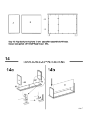
Secure back panels with Small Wood Screws (H6). 14 14a DRAWER ASSEMBLY INSTRUCTIONS 14b R page 7 Step 13: Align back panels (J and K) onto back of the assembled chifferobe.
Secure back panels with Small Wood Screws (H6). 14 14a DRAWER ASSEMBLY INSTRUCTIONS 14b R page 7 Step 13: Align back panels (J and K) onto back of the assembled chifferobe.
Operation Manual
Page 8
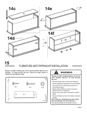
... below to accommodate, do not set TVs or other heavy objects on drawers, doors, or shelves. Use of tip-over restraints may only reduce, but not eliminate, the risk of this anti-tipping strap. page 8 Unless specifically designed to install this product. Never allow children ...to remove! 14c 14e 14f 14d 15 FURNITURE ANTI-TIPPING KIT INSTALLATION Serious or fatal crushing can occur from furniture tip-over. To help prevent ...
... below to accommodate, do not set TVs or other heavy objects on drawers, doors, or shelves. Use of tip-over restraints may only reduce, but not eliminate, the risk of this anti-tipping strap. page 8 Unless specifically designed to install this product. Never allow children ...to remove! 14c 14e 14f 14d 15 FURNITURE ANTI-TIPPING KIT INSTALLATION Serious or fatal crushing can occur from furniture tip-over. To help prevent ...
Operation Manual
Page 9
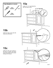
page 9 Tools Needed (not included) Stubby Screwdriver Pencil 15a Locate a 2" x 4" stud behind the wall, and make a mark. 2" x 4" wall stud Phillips screwdriver 15b Install the strap on the wall with long screw and washer. 15c Install the other end of strap on the back of dresser with short screw and washer into the wood framing of the dresser.
page 9 Tools Needed (not included) Stubby Screwdriver Pencil 15a Locate a 2" x 4" stud behind the wall, and make a mark. 2" x 4" wall stud Phillips screwdriver 15b Install the strap on the wall with long screw and washer. 15c Install the other end of strap on the back of dresser with short screw and washer into the wood framing of the dresser.
Operation Manual
Page 10
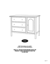
page 10 Finish KEEP THIS MANUAL IN A SAFE PLACE FOR FUTURE REFERENCE. READ ALL INSTRUCTIONS BEFORE USING THE PRODUCT. KEEP THE INSTRUCTIONS FOR FUTURE USE.
page 10 Finish KEEP THIS MANUAL IN A SAFE PLACE FOR FUTURE REFERENCE. READ ALL INSTRUCTIONS BEFORE USING THE PRODUCT. KEEP THE INSTRUCTIONS FOR FUTURE USE.

