User Manual
Page 2
... Mercury series casing include state-of the "3D Mercury" series, please visit Gigabyte Tech. Malfunction due to interference from other computer-related devices. 9. The devices inside, including power supply, hard disk, CD-ROM drive, motherboard, ventilator, etc, are not covered by failure to provide users with in the user manual. Caution Failure to wear gloves during installation of computer products may possibly...
... Mercury series casing include state-of the "3D Mercury" series, please visit Gigabyte Tech. Malfunction due to interference from other computer-related devices. 9. The devices inside, including power supply, hard disk, CD-ROM drive, motherboard, ventilator, etc, are not covered by failure to provide users with in the user manual. Caution Failure to wear gloves during installation of computer products may possibly...
User Manual
Page 3
... Introduction 4 1-1 Casing's Internal Structure 4 1-2 Front, Rear, and Left Side Panel Structure 5 2. Specification Features 8 4. Installation Instruction 9 4-1 Installation of Power Supply 9 4-2 Installation of Motherboard 11 4-3 Installation of Add on Card 12 4-4 Installation of Front Multi-Media I/O Ports 13 4-5 Connection of Fan Power Cables 14 4-6 Installation of 5.25" Front Device Bay 15 4-7 Installation of 3.5" Front Device Bay 15 4-8 Installation of 3.5" Internal Device Bay 15 4-9 Application of Security Lock 16 4-10 Application of Foot Supports 16...
... Introduction 4 1-1 Casing's Internal Structure 4 1-2 Front, Rear, and Left Side Panel Structure 5 2. Specification Features 8 4. Installation Instruction 9 4-1 Installation of Power Supply 9 4-2 Installation of Motherboard 11 4-3 Installation of Add on Card 12 4-4 Installation of Front Multi-Media I/O Ports 13 4-5 Connection of Fan Power Cables 14 4-6 Installation of 5.25" Front Device Bay 15 4-7 Installation of 3.5" Front Device Bay 15 4-8 Installation of 3.5" Internal Device Bay 15 4-9 Application of Security Lock 16 4-10 Application of Foot Supports 16...
User Manual
Page 4
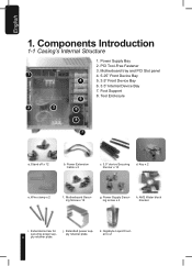
... d. Wire clamp x 2 f. j. English 1. Motherboard Securing Screw x 12 g. Extended screw for securing power sup- 4 ply retainer plate. Extended power supply retainer plate. k. Power Supply Bay 2. Stand off x 12 b. Power Supply Securing screw x 4 h. Motherboard tray and PCI Slot panel 1 4. 5.25" Front Device Bay 4 5. 3.5" Front Device Bay 6. 3.5" Internal Device Bay 7. AM2 Water block bracket i. Key x 2 e. Tool Enclosure 5 2 3 6 8 7 a. Components Introduction 1-1 Casing's Internal Structure 1. Gigabyte Liquid Coolant x 2 Foot Support 8.
... d. Wire clamp x 2 f. j. English 1. Motherboard Securing Screw x 12 g. Extended screw for securing power sup- 4 ply retainer plate. Extended power supply retainer plate. k. Power Supply Bay 2. Stand off x 12 b. Power Supply Securing screw x 4 h. Motherboard tray and PCI Slot panel 1 4. 5.25" Front Device Bay 4 5. 3.5" Front Device Bay 6. 3.5" Internal Device Bay 7. AM2 Water block bracket i. Key x 2 e. Tool Enclosure 5 2 3 6 8 7 a. Components Introduction 1-1 Casing's Internal Structure 1. Gigabyte Liquid Coolant x 2 Foot Support 8.

User Manual
Page 5
English 9. IEEE1394 (Multi-connectors) d. 3-Pin Fan Connector e. Motherboard 2-pin connector and 4-pin connector to power supply. 1-2 Front, Rear, and Left Side Panel Structure a) Left Side Panel Side Grill for LCS air intake Latch Left Side Panel Security Lock Transparent/Mesh Side Panel 5 Power SW/Reset SW/HDD LED Connector f. Audio (HD & AC97) c. USB 2.0 x 2 b. Front Cable Kit a.
English 9. IEEE1394 (Multi-connectors) d. 3-Pin Fan Connector e. Motherboard 2-pin connector and 4-pin connector to power supply. 1-2 Front, Rear, and Left Side Panel Structure a) Left Side Panel Side Grill for LCS air intake Latch Left Side Panel Security Lock Transparent/Mesh Side Panel 5 Power SW/Reset SW/HDD LED Connector f. Audio (HD & AC97) c. USB 2.0 x 2 b. Front Cable Kit a.
User Manual
Page 6
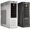
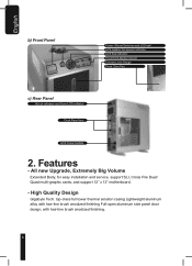
... easy installation and service, support SLI, Cross Fire Dual/ Quad multi-graphic cards, and support 12" x 13" motherboard. - English b) Front Panel Power / Reset Switches and LED light LCS radiator fan speed controller LCS flow indicator Front Multi-Media I/O port Coolant Level Gauge Front 12cm Fan c) Rear Panel Hot air release vent from LCS radiator Dual Rear fans LCS Tube Outlets 2. top-class full tower thermal solution casing...
... easy installation and service, support SLI, Cross Fire Dual/ Quad multi-graphic cards, and support 12" x 13" motherboard. - English b) Front Panel Power / Reset Switches and LED light LCS radiator fan speed controller LCS flow indicator Front Multi-Media I/O port Coolant Level Gauge Front 12cm Fan c) Rear Panel Hot air release vent from LCS radiator Dual Rear fans LCS Tube Outlets 2. top-class full tower thermal solution casing...
User Manual
Page 7
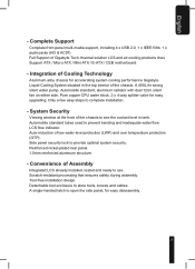
... motherboard. - Pure copper CPU water block. 2 x 4-way splitter valve for easy disassembly. 7 Convenience of the chassis. A 400L/hr strong silent water pump. Automobile standard, aluminum radiator with dual 12cm silent fan on either side. Complete Support Complete front panel multi-media support, including 4 x USB 2.0, 1 x IEEE1394, 1 x audio jacks (HD & AC97) Full Support of Gigabyte Tech. LCS flow indicator. Tool-free installation design...
... motherboard. - Pure copper CPU water block. 2 x 4-way splitter valve for easy disassembly. 7 Convenience of the chassis. A 400L/hr strong silent water pump. Automobile standard, aluminum radiator with dual 12cm silent fan on either side. Complete Support Complete front panel multi-media support, including 4 x USB 2.0, 1 x IEEE1394, 1 x audio jacks (HD & AC97) Full Support of Gigabyte Tech. LCS flow indicator. Tool-free installation design...
User Manual
Page 9
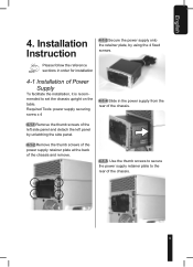
... of the chassis. 9 Installation Instruction 4-1-3 Secure the power supply onto the retainer plate, by unlatching the side panel. 4-1-2 Remove the thumb screws of the power supply retainer plate at the back of the chassis and remove. 4-1-5 Use the thumb screws to secure the power supply retainer plate to set the chassis upright on the table. Required Tools: power supply securing screw x 4 4-1-4 Slide in order for installation 4-1 Installation of the...
... of the chassis. 9 Installation Instruction 4-1-3 Secure the power supply onto the retainer plate, by unlatching the side panel. 4-1-2 Remove the thumb screws of the power supply retainer plate at the back of the chassis and remove. 4-1-5 Use the thumb screws to secure the power supply retainer plate to set the chassis upright on the table. Required Tools: power supply securing screw x 4 4-1-4 Slide in order for installation 4-1 Installation of the...

User Manual
Page 10
English 4-1-6 If a longer power supply is used which obstructs the product's sliding through the rear, please install the power according to the coolant tank. 4-1-7a Remove the thumb screws of the side panels and detach both side panels. 4-1-7b Remove the thumb screws of the power retainer plate at the rear and two on the top cover of the chassis, two at...
English 4-1-6 If a longer power supply is used which obstructs the product's sliding through the rear, please install the power according to the coolant tank. 4-1-7a Remove the thumb screws of the side panels and detach both side panels. 4-1-7b Remove the thumb screws of the power retainer plate at the rear and two on the top cover of the chassis, two at...

User Manual
Page 11
... to reassemble the parts 4-2 Installation of Motherboard 3D Mercury can support ATX / Micro ATX / Mini ATX / E-ATX / CEB Please confirm the motherboard screw holes locations and size specification before installation Required Tools: Screwdriver, stand offs, and the motherboard screws 4-1-7g Gently lift the liquid cooling system tray and insert the power supply through the rear chassis. 4-2-1 First remove the CPU water block from...
... to reassemble the parts 4-2 Installation of Motherboard 3D Mercury can support ATX / Micro ATX / Mini ATX / E-ATX / CEB Please confirm the motherboard screw holes locations and size specification before installation Required Tools: Screwdriver, stand offs, and the motherboard screws 4-1-7g Gently lift the liquid cooling system tray and insert the power supply through the rear chassis. 4-2-1 First remove the CPU water block from...
User Manual
Page 12
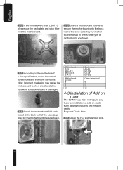
... add-on cards such as graphics cards and network cards. Motherboard ATX Mini ATX Micro ATX E-ATX Motherboard screws 9 9 9 12 Code name A1-A9 M1-M9 U1-U9 E1-E12 Case copper post 9 9 9 12 4-3 Installation of Add on Card The 3D Mercury does not require any tools for installation of the case (supplied by the motherboard manufacturer). Required Tools: None 4-3-1 Open the PCI slot...
... add-on cards such as graphics cards and network cards. Motherboard ATX Mini ATX Micro ATX E-ATX Motherboard screws 9 9 9 12 Code name A1-A9 M1-M9 U1-U9 E1-E12 Case copper post 9 9 9 12 4-3 Installation of Add on Card The 3D Mercury does not require any tools for installation of the case (supplied by the motherboard manufacturer). Required Tools: None 4-3-1 Open the PCI slot...
User Manual
Page 13
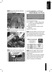
... 1 Power 6 USB Dy+ 2 Power 7 GND 3 USB Dx- 8 GND 4 USB Dy- 9 5 USB Dx+ 10 USB Over current 4-4-2 Insert the IEEE 1394 connector into the corresponding socket on the motherboard (please refer to the motherboard user manual for further information). Please refer to the instructions supplied by the motherboard manufacturer and make sure the card is used prior to installation. 13 English 4-3-2 Remove the internally attached dust proof PCI cover...
... 1 Power 6 USB Dy+ 2 Power 7 GND 3 USB Dx- 8 GND 4 USB Dy- 9 5 USB Dx+ 10 USB Over current 4-4-2 Insert the IEEE 1394 connector into the corresponding socket on the motherboard (please refer to the motherboard user manual for further information). Please refer to the instructions supplied by the motherboard manufacturer and make sure the card is used prior to installation. 13 English 4-3-2 Remove the internally attached dust proof PCI cover...

User Manual
Page 14
...Power SW Red (+)/White (-) H.D.D. board. HD AUDIO Reminder, Different Motherboards have different installation areas and specifications, screw holes and connectors. Please read the motherboard user manual supplied by the motherboard manufacturer 4-5 Connection of Fan Power Cables The 3D Mercury has one 12cm silent, blue LED cooling fan... 2 GND 7 NC 3 MIC Power 8 NO Pin 4 NC 9 Line Out(L) 5 Line Out(R) 10 NC 4-4-4 Basic casing power switch control cable kit. LED Brown (+)/White (-) 4-4-5 Power switch connector, LCS power supply (including LCS emergency shutdown). Pin ...
...Power SW Red (+)/White (-) H.D.D. board. HD AUDIO Reminder, Different Motherboards have different installation areas and specifications, screw holes and connectors. Please read the motherboard user manual supplied by the motherboard manufacturer 4-5 Connection of Fan Power Cables The 3D Mercury has one 12cm silent, blue LED cooling fan... 2 GND 7 NC 3 MIC Power 8 NO Pin 4 NC 9 Line Out(L) 5 Line Out(R) 10 NC 4-4-4 Basic casing power switch control cable kit. LED Brown (+)/White (-) 4-4-5 Power switch connector, LCS power supply (including LCS emergency shutdown). Pin ...
User Manual
Page 15
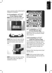
...panel of the case and remove the mesh drive rail and metal EMI plate of the chassis. Refer to step 4-6. 4-8 Installation of 3.5" Internal Device Bay The 3D Mercury provides built-in the 5.25" device into the internal drive bay. 15 Required Tools: Securing runners (2 per hard disc drive) 4-8-1 Fit the securing runners on the motherboard to 5 hard disc drives (after removal... in the black tool enclosure. English power connector on both sides of the HDD and slide the HDD into the drive bay from the front of the chassis and level it with the other mesh drive rails. 4-6-3 Secure the 5.25" ...
...panel of the case and remove the mesh drive rail and metal EMI plate of the chassis. Refer to step 4-6. 4-8 Installation of 3.5" Internal Device Bay The 3D Mercury provides built-in the 5.25" device into the internal drive bay. 15 Required Tools: Securing runners (2 per hard disc drive) 4-8-1 Fit the securing runners on the motherboard to 5 hard disc drives (after removal... in the black tool enclosure. English power connector on both sides of the HDD and slide the HDD into the drive bay from the front of the chassis and level it with the other mesh drive rails. 4-6-3 Secure the 5.25" ...
User Manual
Page 16
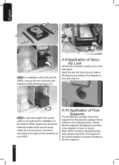
... case the length of the power cable is not sufficient for ensuring the casing is firmly seated on the side panel. Swivel the foot supports 90 degrees according to the diagram to prevent bending of the foot supports. 16 Note: When moving or laying down the case, please swivel the foot support ...to the closed position to open or retract. English 4-8-2 For installation of the 4th and 5th HDDs, remove...
... case the length of the power cable is not sufficient for ensuring the casing is firmly seated on the side panel. Swivel the foot supports 90 degrees according to the diagram to prevent bending of the foot supports. 16 Note: When moving or laying down the case, please swivel the foot support ...to the closed position to open or retract. English 4-8-2 For installation of the 4th and 5th HDDs, remove...

User Manual
Page 17
... side panel window out from the carton box and remove the plastic protection layer. English 4-11 Application of Liquid Cooling System 4-12-1 CPU water block installation Warning: Be sure to remove the "CAUTION" sticker from the mesh grid. e. b. a. Open the side panel and lay it on the CPU surface. 17 Screw the transparent side panel window onto the side panel with...
... side panel window out from the carton box and remove the plastic protection layer. English 4-11 Application of Liquid Cooling System 4-12-1 CPU water block installation Warning: Be sure to remove the "CAUTION" sticker from the mesh grid. e. b. a. Open the side panel and lay it on the CPU surface. 17 Screw the transparent side panel window onto the side panel with...

User Manual
Page 19
... block is properly secured on the CPU. 4-12-5 Mosfet Air-Cooling Fan installation. 4-12-5-1 Place the Mosfet air-cooling fan on the top of the water block and make sure that the four feet of the air-cooling fan are secured on the water block. 4-12-4 AM2 Clip Cover Installation 4-12-4-1 Replace the clip cover on the... water block to the raised points on the CPU. 19 Align the AMD AM2 clip to the AMD AM2 clip cover.
... block is properly secured on the CPU. 4-12-5 Mosfet Air-Cooling Fan installation. 4-12-5-1 Place the Mosfet air-cooling fan on the top of the water block and make sure that the four feet of the air-cooling fan are secured on the water block. 4-12-4 AM2 Clip Cover Installation 4-12-4-1 Replace the clip cover on the... water block to the raised points on the CPU. 19 Align the AMD AM2 clip to the AMD AM2 clip cover.
User Manual
Page 20
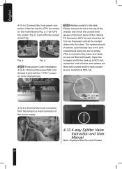
... the power supply. 4-13 4-way Splitter Valve Instruction and User Manual Note: Gigabyte Blue Eye and Chipset 20 Open the lid again and fill the tank up to 80% full and close the lid. Fill the tank to 80% full; Turn on the power until all the coolant drains into the CPU fan socket on the motherboard (Fig. a: 3-pin CPU fan socket...
... the power supply. 4-13 4-way Splitter Valve Instruction and User Manual Note: Gigabyte Blue Eye and Chipset 20 Open the lid again and fill the tank up to 80% full and close the lid. Fill the tank to 80% full; Turn on the power until all the coolant drains into the CPU fan socket on the motherboard (Fig. a: 3-pin CPU fan socket...
User Manual
Page 23
... next to improper installation may damage the system and is not covered by warranty. Fig. Note: It is strongly recommended that all the coolant. Although this has already been tested before the product is dispatched from any damage arising from the chassis. any electronic part. English turn off...the empty container on power to prevent leakage if it is turned off the power and keep all the devices away from the factory, the chassis is not covered by warranty. 4-13-8 Draining out all the power is dropped or damaged. Using the screwdriver, remove the bottom 4-way ...
... next to improper installation may damage the system and is not covered by warranty. Fig. Note: It is strongly recommended that all the coolant. Although this has already been tested before the product is dispatched from any damage arising from the chassis. any electronic part. English turn off...the empty container on power to prevent leakage if it is turned off the power and keep all the devices away from the factory, the chassis is not covered by warranty. 4-13-8 Draining out all the power is dropped or damaged. Using the screwdriver, remove the bottom 4-way ...

User Manual
Page 24
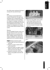
You will need to be replaced. 4-14 Liquid Cooling System Maintenance 4-14-1 If If the coolant level is to low, remove the top lid and, after refilling coolant, secure the lid back on either side of the chassis, two at the rear and two on . 4-14-2 If pump ...to drain the coolant from the top of the tubes. Remove the 4 screws that need tools for this. After all the coolant has been drained out. English Fig. a. C f. g. Remove the lid from the chassis. b. Please use the above-mentioned method to transport the chassis or replace parts that secure the tank. c. d.
You will need to be replaced. 4-14 Liquid Cooling System Maintenance 4-14-1 If If the coolant level is to low, remove the top lid and, after refilling coolant, secure the lid back on either side of the chassis, two at the rear and two on . 4-14-2 If pump ...to drain the coolant from the top of the tubes. Remove the 4 screws that need tools for this. After all the coolant has been drained out. English Fig. a. C f. g. Remove the lid from the chassis. b. Please use the above-mentioned method to transport the chassis or replace parts that secure the tank. c. d.

User Manual
Page 26
d. GIGABYTE Chipset Water block - Replace the parts that hold the front panel onto the chassis, and remove the front panel. b. Take out the fan holder and separate the fan holder from the fan. 26 English k. a. GIGABYTE VGA Air Cooler - Recommended parts to reassemble. l. Remove the pump and tank. Open the two side panels. Release the plastic clamps that need to be replaced, reverse steps to reassemble...
d. GIGABYTE Chipset Water block - Replace the parts that hold the front panel onto the chassis, and remove the front panel. b. Take out the fan holder and separate the fan holder from the fan. 26 English k. a. GIGABYTE VGA Air Cooler - Recommended parts to reassemble. l. Remove the pump and tank. Open the two side panels. Release the plastic clamps that need to be replaced, reverse steps to reassemble...