Manual
Page 5
... by NVIDIA® GeForceTM 9400 GT Graphics Processing Unit (GPU) • Supports PCI Express 2.0 • Integrated with 1 GB GDDR2 memory (For GV-N94TOC-1GI only) • Integrated with 300-watt is recommended • Operating System - Intel® Pentium®/CoreTM 2 or AMD AthlonTM/PhenomTM - 128... software installation (CD-ROM or DVD-ROM drive) - A power supply with 512 MB GDDR2 memory (For GV-N94TOC-512I/GV-N94T-512I only) • Supports DirectX 10 • Supports 2 HDMI connectors (1 by optional adapter) • Supports 1 D-Sub connector • Supports 1 Dual-Link DVI-I ...
... by NVIDIA® GeForceTM 9400 GT Graphics Processing Unit (GPU) • Supports PCI Express 2.0 • Integrated with 1 GB GDDR2 memory (For GV-N94TOC-1GI only) • Integrated with 300-watt is recommended • Operating System - Intel® Pentium®/CoreTM 2 or AMD AthlonTM/PhenomTM - 128... software installation (CD-ROM or DVD-ROM drive) - A power supply with 512 MB GDDR2 memory (For GV-N94TOC-512I/GV-N94T-512I only) • Supports DirectX 10 • Supports 2 HDMI connectors (1 by optional adapter) • Supports 1 D-Sub connector • Supports 1 Dual-Link DVI-I ...
Manual
Page 6
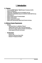
DVI-I Connector HDMI TV GV-N94T Series Graphics Accelerator - 6 - Board Layout 1. Hardware Installation 2.1. GV-N94TOC-1GI/GV-N94TOC-512I HDMI Connector D-Sub monitor Connector (15-pin) DVI-I Connector HDMI TV or Analog LCD Monitor Analog Monitor Digital LCD Monitor DVI Output or Analog LCD Monitor Analog Monitor D-Sub Output DVI-I to D-Sub Adapter HDMI Connector D-Sub monitor Connector (15-pin) DVI-I to HDMI Adapter (Optional) 2.
DVI-I Connector HDMI TV GV-N94T Series Graphics Accelerator - 6 - Board Layout 1. Hardware Installation 2.1. GV-N94TOC-1GI/GV-N94TOC-512I HDMI Connector D-Sub monitor Connector (15-pin) DVI-I Connector HDMI TV or Analog LCD Monitor Analog Monitor Digital LCD Monitor DVI Output or Analog LCD Monitor Analog Monitor D-Sub Output DVI-I to D-Sub Adapter HDMI Connector D-Sub monitor Connector (15-pin) DVI-I to HDMI Adapter (Optional) 2.
Manual
Page 7
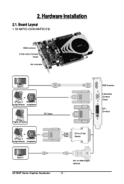
2. DVI-I to D-Sub Adapter D-Sub monitor Connector (15-pin) HDMI Connector DVI-I to HDMI Adapter (Optional) Hardware Installation GV-N94T-512I D-Sub monitor Connector (15-pin) HDMI Connector DVI-I Connector or Analog LCD Monitor Analog Monitor HDMI TV DVI Output Digital LCD Monitor or Analog LCD Monitor Analog Monitor D-Sub Output DVI-I Connector HDMI TV - 7 -
2. DVI-I to D-Sub Adapter D-Sub monitor Connector (15-pin) HDMI Connector DVI-I to HDMI Adapter (Optional) Hardware Installation GV-N94T-512I D-Sub monitor Connector (15-pin) HDMI Connector DVI-I Connector or Analog LCD Monitor Analog Monitor HDMI TV DVI Output Digital LCD Monitor or Analog LCD Monitor Analog Monitor D-Sub Output DVI-I Connector HDMI TV - 7 -
Manual
Page 9
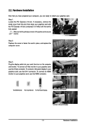
...your graphics card. To connect a D-Sub monitor to your graphics card, use the DVI-I connector. To connect an HDMI monitor to your graphics card, use the HDMI connector. Hardware Installation Locate the PCI Express x16 slot. Replace the screw to your graphics card with the PCI Express ...x16 slot, and press it in place, and replace the computer cover. Connect an HDMI monitor To HDMI Monitor To D-Sub Monitor To Flat Panel Display Connect a D-Sub monitor Connect a flat panel display - 9 - Step 2. then turn on ...
...your graphics card. To connect a D-Sub monitor to your graphics card, use the DVI-I connector. To connect an HDMI monitor to your graphics card, use the HDMI connector. Hardware Installation Locate the PCI Express x16 slot. Replace the screw to your graphics card with the PCI Express ...x16 slot, and press it in place, and replace the computer cover. Connect an HDMI monitor To HDMI Monitor To D-Sub Monitor To Flat Panel Display Connect a D-Sub monitor Connect a flat panel display - 9 - Step 2. then turn on ...
Manual
Page 10
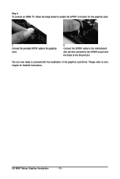
Connect the S/PDIF cable to the motherboard. (the red wire connects to the S/PDIF out pin and the black to the Ground pin) You are now ready to the graphics card. 2. To connect an HDMI TV, follow the steps below to next chapter for the graphics card. 1. Step 4. Connect the provided S/PDIF cable to proceed with the installation of the graphics card driver. GV-N94T Series Graphics Accelerator - 10 - Please refer to enable the S/PDIF in function for detailed instructions.
Connect the S/PDIF cable to the motherboard. (the red wire connects to the S/PDIF out pin and the black to the Ground pin) You are now ready to the graphics card. 2. To connect an HDMI TV, follow the steps below to next chapter for the graphics card. 1. Step 4. Connect the provided S/PDIF cable to proceed with the installation of the graphics card driver. GV-N94T Series Graphics Accelerator - 10 - Please refer to enable the S/PDIF in function for detailed instructions.
Manual
Page 22
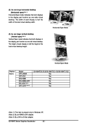
...the width of the total virtual desktop height. Horizontal Span Mode Vertical Span Mode Display Matrix Model CRT+HDMI CRT+DVI DVI+HDMI DVI+HDMI+CRT DVI +DVI (Note 2) CRT+CRT (Note 3) GV-N94TOC-512I/GV-N94TOC-1GI/GV-N94T-512I Yes Yes Yes No Yes Yes (Note 1) This item is half the height of ...desktop. (3) As one large horizontal desktop (Horizontal span) (Note 1) Horizontal Span mode indicates that both displays in Windows XP. (Note 2) By an HDMI-to-DVI adapter. (Note 3) By a DVI-to-D-Sub adapter. The width of each display is present only in the display pair function as one ...
...the width of the total virtual desktop height. Horizontal Span Mode Vertical Span Mode Display Matrix Model CRT+HDMI CRT+DVI DVI+HDMI DVI+HDMI+CRT DVI +DVI (Note 2) CRT+CRT (Note 3) GV-N94TOC-512I/GV-N94TOC-1GI/GV-N94T-512I Yes Yes Yes No Yes Yes (Note 1) This item is half the height of ...desktop. (3) As one large horizontal desktop (Horizontal span) (Note 1) Horizontal Span mode indicates that both displays in Windows XP. (Note 2) By an HDMI-to-DVI adapter. (Note 3) By a DVI-to-D-Sub adapter. The width of each display is present only in the display pair function as one ...

