
Installation Guide
Page 2
... Hardware Installation 12 Step 3-1: Chassis Removal and Installation 12 Step 3-2: CPU Installation 13 Step 3-3: Heat Sink Installation 14 Step 3-4: Memory Installation 14 Step 3-5: PCI Expansion Card Installation 15 Step 3-6: Hard Disk Drive Installation 16 Step 3-7: FAN Duct Removal and Installation 17 Chapter 4 Appearance of GS-R114V 18 4-1: Front View of GS-R114V 18 4-2: Rear View of GS-R114V 19 4-3: Switch and LED Indicators Introduction 20 4-4: LAN LED Description 21 4-5 : Connector Icon Description 22 Chapter 5 Motherboard Layout & Jumper Setting 23...
... Hardware Installation 12 Step 3-1: Chassis Removal and Installation 12 Step 3-2: CPU Installation 13 Step 3-3: Heat Sink Installation 14 Step 3-4: Memory Installation 14 Step 3-5: PCI Expansion Card Installation 15 Step 3-6: Hard Disk Drive Installation 16 Step 3-7: FAN Duct Removal and Installation 17 Chapter 4 Appearance of GS-R114V 18 4-1: Front View of GS-R114V 18 4-2: Rear View of GS-R114V 19 4-3: Switch and LED Indicators Introduction 20 4-4: LAN LED Description 21 4-5 : Connector Icon Description 22 Chapter 5 Motherboard Layout & Jumper Setting 23...

Installation Guide
Page 3
Table of Content Advanced 33 Memory Configuration ...34 PCI Configuration ...35 I/O Device Configuration 37 Advanced Chipset Control 42 Hardware Monitor ...44 Security ...46 Server ...48 System Management ...49 Console Redirection ...50 Boot ...53 Exit ...54 Chapter 6 Driver Installation 58 A.Intel Chipset Software Installation Utilities 58 B.Intel LAN Driver Installation 60 C.Intel Host RAID Driver Installation 62 D.VGA ES100 Driver Installation 64 E.DirectX 9.0 Driver Installation 65 Chapter 7 Appendix 66 7-1: Acronyms ...66 3
Table of Content Advanced 33 Memory Configuration ...34 PCI Configuration ...35 I/O Device Configuration 37 Advanced Chipset Control 42 Hardware Monitor ...44 Security ...46 Server ...48 System Management ...49 Console Redirection ...50 Boot ...53 Exit ...54 Chapter 6 Driver Installation 58 A.Intel Chipset Software Installation Utilities 58 B.Intel LAN Driver Installation 60 C.Intel Host RAID Driver Installation 62 D.VGA ES100 Driver Installation 64 E.DirectX 9.0 Driver Installation 65 Chapter 7 Appendix 66 7-1: Acronyms ...66 3

Installation Guide
Page 4
... cool before removing covers or touching internal components. Never insert objects of any kind into a grounding-type power outlet. There may be in the case are provided for ventilation. GS-R114V Rack Mount Server Safety, Care and Regulatory Information Important safety information Read and follow all instructions marked on the product and in the product's documentation. * Only authorized service technicians should...
... cool before removing covers or touching internal components. Never insert objects of any kind into a grounding-type power outlet. There may be in the case are provided for ventilation. GS-R114V Rack Mount Server Safety, Care and Regulatory Information Important safety information Read and follow all instructions marked on the product and in the product's documentation. * Only authorized service technicians should...

Installation Guide
Page 5
...installed and used in order to products fitted with USA modems) The modem complies with Part 68 of the FCC Rules. Operation of this equipment in a residential area is subject to the following two conditions: (1) this equipment. Operation is likely to cause harmful interference in which case the user... found to comply with the instruction manual, may discontinue your right to operate the equipment. These limits are in the vicinity of the leak. Properly shielded and grounded cables and connectors must be informed of your service temporarily. FCC part 68 (applicable to meet FCC...
...installed and used in order to products fitted with USA modems) The modem complies with Part 68 of the FCC Rules. Operation of this equipment in a residential area is subject to the following two conditions: (1) this equipment. Operation is likely to cause harmful interference in which case the user... found to comply with the instruction manual, may discontinue your right to operate the equipment. These limits are in the vicinity of the leak. Properly shielded and grounded cables and connectors must be informed of your service temporarily. FCC part 68 (applicable to meet FCC...

Installation Guide
Page 6
... products fitted with the above conditions might not prevent degradation of service in some situations. Any repairs or alterations made by an authorized Canadian maintenance facility designated by the user to this equipment, or equipment malfunctions, may give you will operate to make changes in the radio interference regulations of your equipment. GS-R114V Rack Mount Server Your...
... products fitted with the above conditions might not prevent degradation of service in some situations. Any repairs or alterations made by an authorized Canadian maintenance facility designated by the user to this equipment, or equipment malfunctions, may give you will operate to make changes in the radio interference regulations of your equipment. GS-R114V Rack Mount Server Your...

Installation Guide
Page 8
.... ; Cables (RJ45) ; ; GA-4MPSV Motherboard (Installed) GSMT User's Manual CPU Heat Sink x 1 Silm type CD-ROM drive (Installed) GS-R114V System Installation Guide Driver CD for future reference. If any component is switched off before handling computer components. FAN Duct x 1 ; ; Place components on a grounded antistatic pad or on the inside. 2. GS-R114V Rack Mount Server Introduction Welcome to verify the contents. The guide provides instructions for configuration hardware for the sever...
.... ; Cables (RJ45) ; ; GA-4MPSV Motherboard (Installed) GSMT User's Manual CPU Heat Sink x 1 Silm type CD-ROM drive (Installed) GS-R114V System Installation Guide Driver CD for future reference. If any component is switched off before handling computer components. FAN Duct x 1 ; ; Place components on a grounded antistatic pad or on the inside. 2. GS-R114V Rack Mount Server Introduction Welcome to verify the contents. The guide provides instructions for configuration hardware for the sever...

Installation Guide
Page 10
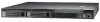
GS-R114V Rack Mount Server Super I/O Controller ITE IT8712FIX-A Super I/O Built-in I/O 1 x Serial port (COM) 2 x USB 2.0 dual-port connector (1 at front panel) 1 x VGA connector 2 x RJ45 LAN ports P/S 2 Keyboard and Mouse Connectors 1 x RJ45 on front for console redirection System BIOS: BIOS Type Phoenix® BIOS, Multi-boot BBS 1.0 Compliant 8Mb Flash Memory Special Features BIOS HW Monitoring reporting (The values monitored by HW Monitoring...
GS-R114V Rack Mount Server Super I/O Controller ITE IT8712FIX-A Super I/O Built-in I/O 1 x Serial port (COM) 2 x USB 2.0 dual-port connector (1 at front panel) 1 x VGA connector 2 x RJ45 LAN ports P/S 2 Keyboard and Mouse Connectors 1 x RJ45 on front for console redirection System BIOS: BIOS Type Phoenix® BIOS, Multi-boot BBS 1.0 Compliant 8Mb Flash Memory Special Features BIOS HW Monitoring reporting (The values monitored by HW Monitoring...

Installation Guide
Page 13
... properly inserted, please replace the plastic covering and push the metal lever back into the socket in a straight and downwards motion. Hardware Installation Process Step 3-2: CPU Installation Please make sure the CPU type and speed that might cause damage to the upper-right position. Avoid twisting or bending motions that are supported by the motherboard. Step 1 Gently...
... properly inserted, please replace the plastic covering and push the metal lever back into the socket in a straight and downwards motion. Hardware Installation Process Step 3-2: CPU Installation Please make sure the CPU type and speed that might cause damage to the upper-right position. Avoid twisting or bending motions that are supported by the motherboard. Step 1 Gently...

Installation Guide
Page 16
Connect cable and power. Step 3 Slide hard disk into blank and secure it locks into place. Step 4 To replace the hard drive blank, slide the blank into the server system. Step 1 Step 2 Step 3 16 Step 5 Place the hard disk into the bay until it with screws. Step 2 Remove the plastic hard disk tray. GS-R114V Rack Mount Server Step 3-6: Hard Disk Drive Installation Step 1 Press the release button and pull the blank out of the drive bay.
Connect cable and power. Step 3 Slide hard disk into blank and secure it locks into place. Step 4 To replace the hard drive blank, slide the blank into the server system. Step 1 Step 2 Step 3 16 Step 5 Place the hard disk into the bay until it with screws. Step 2 Remove the plastic hard disk tray. GS-R114V Rack Mount Server Step 3-6: Hard Disk Drive Installation Step 1 Press the release button and pull the blank out of the drive bay.

Installation Guide
Page 20
GS-R114V Rack Mount Server 4-3: Switch and LED Indicators Introduction HDD Fail Warning Status HDD Power/Sleep Name Power Status Color Green Green -Green Amber Amber -- LAN1/2 Activities ID NMI Condition Description On Power On Blink Sleep (S1) Off Power Off (S4/S5) On System Ready On/ Alarm Blink System Ready but deqraded, CPU...On Critical Alarm: Critical Power Module Failure, Critical FANs Failure, Voltage (Power Supply) Critical Temperature and Voltage Off System Not Ready/ Post error/NMI event/CPU or terminator missing Blink Hard Disk Drive Access On HDD Fault Off...
GS-R114V Rack Mount Server 4-3: Switch and LED Indicators Introduction HDD Fail Warning Status HDD Power/Sleep Name Power Status Color Green Green -Green Amber Amber -- LAN1/2 Activities ID NMI Condition Description On Power On Blink Sleep (S1) Off Power Off (S4/S5) On System Ready On/ Alarm Blink System Ready but deqraded, CPU...On Critical Alarm: Critical Power Module Failure, Critical FANs Failure, Voltage (Power Supply) Critical Temperature and Voltage Off System Not Ready/ Post error/NMI event/CPU or terminator missing Blink Hard Disk Drive Access On HDD Fault Off...

Installation Guide
Page 26
... Power ON the computer and press immediately will allow you to the item in the right hand Main Menu - This type of the BIOS Setup Program. Quit and not save changes into CMOS Status Page Setup Menu and Option Page Setup Menu - GS-R114V Rack Mount Server Chapter 6 BIOS Setup BIOS Setup ...is turned off. CONTROL KEYS Move to previous item Move to next item Move to the item in battery-backed CMOS RAM so that allows users to Main Menu Increase...
... Power ON the computer and press immediately will allow you to the item in the right hand Main Menu - This type of the BIOS Setup Program. Quit and not save changes into CMOS Status Page Setup Menu and Option Page Setup Menu - GS-R114V Rack Mount Server Chapter 6 BIOS Setup BIOS Setup ...is turned off. CONTROL KEYS Move to previous item Move to next item Move to the item in battery-backed CMOS RAM so that allows users to Main Menu Increase...

Installation Guide
Page 30
GS-R114V Rack Mount Server TYPE 1-39: Predefined types. Multi-Sector Transfer This field displays the information of Teansfer Mode. This field shows the information of Multi-Sector Transfer Mode. Auto: Set parameters automatically. (Default Vaules) CD-ROM: Use for ATAPI CD-ROM drives or double click [Auto] to max ...DMA Mode This field shows if the device type in the specific IDE channel. 30 Disabled: The data transfer from and to the device occurs one sector at a time if the device supports it. Users: Set parameters by User. This filed displays the DMA mode of the device in ...
GS-R114V Rack Mount Server TYPE 1-39: Predefined types. Multi-Sector Transfer This field displays the information of Teansfer Mode. This field shows the information of Multi-Sector Transfer Mode. Auto: Set parameters automatically. (Default Vaules) CD-ROM: Use for ATAPI CD-ROM drives or double click [Auto] to max ...DMA Mode This field shows if the device type in the specific IDE channel. 30 Disabled: The data transfer from and to the device occurs one sector at a time if the device supports it. Users: Set parameters by User. This filed displays the DMA mode of the device in ...

Installation Guide
Page 31
...BIOS Setup Figure 1-1: Advanced Processor Option Advanced Processor Option This category includes the information of CPU Speed, Processor ID, Processor L2 Cache. Disabled Disables C1 Enhanced Mode. (Default value) 31 And setup menu for C1 Enhanced Mode, No Execute Mode Memory Protection, and Processor Power... Management. Disables Processor Reset function. (Default value) C1 Enhanced Mode With enabling C1 Enhanced Mode, all processors on next boot. Processor Reset Yes No Select 'Yes' BIOS ...
...BIOS Setup Figure 1-1: Advanced Processor Option Advanced Processor Option This category includes the information of CPU Speed, Processor ID, Processor L2 Cache. Disabled Disables C1 Enhanced Mode. (Default value) 31 And setup menu for C1 Enhanced Mode, No Execute Mode Memory Protection, and Processor Power... Management. Disables Processor Reset function. (Default value) C1 Enhanced Mode With enabling C1 Enhanced Mode, all processors on next boot. Processor Reset Yes No Select 'Yes' BIOS ...

Installation Guide
Page 38
.... 2F8 Set IO address to 2F8. (Default value) 3E8 Set IO address to 3E8. 2E8 Set IO address to support bi-directional transfers on the parallel port. (Default value) EPP Using Parallel port as Enhanced Parallel Port. Bi-directional Use this option. GS-R114V Rack Mount Server Serial Port B This allows users to configure serial prot B by using this setting to...
.... 2F8 Set IO address to 2F8. (Default value) 3E8 Set IO address to 3E8. 2E8 Set IO address to support bi-directional transfers on the parallel port. (Default value) EPP Using Parallel port as Enhanced Parallel Port. Bi-directional Use this option. GS-R114V Rack Mount Server Serial Port B This allows users to configure serial prot B by using this setting to...

Installation Guide
Page 40
... native mode for WinXP-SP1+IAA driver supports AHCI mode. Auto Auto detected. (Default value) Serial ATA Set Native mode to either PCI or LPC bus. GS-R114V Rack Mount Server Route Port 80h cycles to Set route port 80h cycles to Serial ATA. ` SATA Controller Mode Option Compatible Mode SATA and PATA drives are auto-detected and placed in...
... native mode for WinXP-SP1+IAA driver supports AHCI mode. Auto Auto detected. (Default value) Serial ATA Set Native mode to either PCI or LPC bus. GS-R114V Rack Mount Server Route Port 80h cycles to Set route port 80h cycles to Serial ATA. ` SATA Controller Mode Option Compatible Mode SATA and PATA drives are auto-detected and placed in...

Installation Guide
Page 47
... floppy drives. You will clear any previously entered password from the CMOS memory. Type the password again and press . You may also press to abort the selection and not enter a specified password or press key to protect against virus. Disabled Disable this option. Password on boot. User Requires user's password to 6 characters in lengh and press . BIOS Setup Set Supervisor Password You can install and...
... floppy drives. You will clear any previously entered password from the CMOS memory. Type the password again and press . You may also press to abort the selection and not enter a specified password or press key to protect against virus. Disabled Disable this option. Password on boot. User Requires user's password to 6 characters in lengh and press . BIOS Setup Set Supervisor Password You can install and...

Installation Guide
Page 60
... icon in "My computer", and execute the setup.exe. System starts to start and show a series of Setup Wizard dialog boxes. Select "Install Base Driver. 3. Intel LAN Driver Installation Insert the driver CD-title that came with your motherboard into your CD-ROM driver, the driver CD-title will auto start the installation. 2. GS-R114V Rack Mount Server B. The CD auto run program starts, Double...
... icon in "My computer", and execute the setup.exe. System starts to start and show a series of Setup Wizard dialog boxes. Select "Install Base Driver. 3. Intel LAN Driver Installation Insert the driver CD-title that came with your motherboard into your CD-ROM driver, the driver CD-title will auto start the installation. 2. GS-R114V Rack Mount Server B. The CD auto run program starts, Double...

Installation Guide
Page 62
... Host RAID Driver" item. (1) Starting make a driver disk. 2. Intel Host RAID Driver Installation Installation Procedures: 1. Select a folder refering to yor operating systsem, select the desired folder. (2) Insert a floppy disk, and double click the self-extractor file. 4.Click "OK". (3) (4) 62 The CD auto run program starts, Double click on the self-extractor file. 5. Driver disk creation completed. GS-R114V Rack Mount Server C. Click...
... Host RAID Driver" item. (1) Starting make a driver disk. 2. Intel Host RAID Driver Installation Installation Procedures: 1. Select a folder refering to yor operating systsem, select the desired folder. (2) Insert a floppy disk, and double click the self-extractor file. 4.Click "OK". (3) (4) 62 The CD auto run program starts, Double click on the self-extractor file. 5. Driver disk creation completed. GS-R114V Rack Mount Server C. Click...

Installation Guide
Page 64
VGA ES100 Driver Installation Insert the driver CD-title that came with your motherboard into your computer. GS-R114V Rack Mount Server D. Installation Procedures: 1. The CD auto run program starts, Double click on "VGA ES1000 Driver" to start and show a series of installation wizards appear. Auto Run window Setup Wizard 2.Click "Next". 1.Click "VGA ES1000 Driver" item. (1) License Aggremment (2) Installation Complete 3.Click "Yes". 4.Click "Finish". (3) (4) 64...
VGA ES100 Driver Installation Insert the driver CD-title that came with your motherboard into your computer. GS-R114V Rack Mount Server D. Installation Procedures: 1. The CD auto run program starts, Double click on "VGA ES1000 Driver" to start and show a series of installation wizards appear. Auto Run window Setup Wizard 2.Click "Next". 1.Click "VGA ES1000 Driver" item. (1) License Aggremment (2) Installation Complete 3.Click "Yes". 4.Click "Finish". (3) (4) 64...

Installation Guide
Page 65
...-title will auto start the installation. 2. BIOS Setup E. Click "Next" to start the installation . (3) 65 4.Click "Finish" to start and show the installation guide. Installation Procedures: 1. If not, please double click the CD-ROM device icon in "My computer", and execute the setup.exe. DirectX 9.0 Driver Installation Insert the driver CD-title that came with your motherboard into your computer. Then, a series...
...-title will auto start the installation. 2. BIOS Setup E. Click "Next" to start the installation . (3) 65 4.Click "Finish" to start and show the installation guide. Installation Procedures: 1. If not, please double click the CD-ROM device icon in "My computer", and execute the setup.exe. DirectX 9.0 Driver Installation Insert the driver CD-title that came with your motherboard into your computer. Then, a series...