
User Manual
Page 2
...devices away from any electronic part. (Please refer to disassembly process instruction) The following are not ...the system will blink. (Please purchase GIGABYTE™ liquid coolant to improper installation. 11. Nonobservance of water inadequacy. ...4. Consequential damage to the product's fault. 6. Any damage arising from other objects due to other devices. 4. Malfunction due to the system arising from casualties (earthquake, thunder, fire, and flood). 7. Any loss caused by the warranty 1. While the water in the user manual...
...devices away from any electronic part. (Please refer to disassembly process instruction) The following are not ...the system will blink. (Please purchase GIGABYTE™ liquid coolant to improper installation. 11. Nonobservance of water inadequacy. ...4. Consequential damage to the product's fault. 6. Any damage arising from other objects due to other devices. 4. Malfunction due to the system arising from casualties (earthquake, thunder, fire, and flood). 7. Any loss caused by the warranty 1. While the water in the user manual...

User Manual
Page 3
... Fan Installation 14 4-15 Pump Power Cord Installation 15 4-16 Fan Speed Control Box and Power Cord Instruction 16 4-17 Fan Speed Control Box Installation 16 4-18 Heat Sink Installation 17 5 Liquid Cooling System Installation and Test 18 5-1 Liquid Cooling System Installation and Test 18 5-2 Radiator Installation 19 6 Liquid Cooling System Disassembly 20 7 4-way Splitter Valve Instruction and User Manual 22...
... Fan Installation 14 4-15 Pump Power Cord Installation 15 4-16 Fan Speed Control Box and Power Cord Instruction 16 4-17 Fan Speed Control Box Installation 16 4-18 Heat Sink Installation 17 5 Liquid Cooling System Installation and Test 18 5-1 Liquid Cooling System Installation and Test 18 5-2 Radiator Installation 19 6 Liquid Cooling System Disassembly 20 7 4-way Splitter Valve Instruction and User Manual 22...

User Manual
Page 5
Pump + Tank Assembly ( 2pcs ) 5 English (17)Pump Power Cord (18)Fan 1 to 2 Power Cord (19)Fan Speed Control Power Cord X8 pcs (20)Heat Sink for Memory X2 pcs (21)Bend Proof Spring X4 pcs (22)Nylon Tie (23)Grease (24)Gigabyte Liquid Coolant X2 (25)Velcro (26)Quick Installtion Guide No.8 Screw: a - Secure PCI Rear Fan Speed Controller ( 1pc ) b - Secure Radiator ( 3pcs ) c -
Pump + Tank Assembly ( 2pcs ) 5 English (17)Pump Power Cord (18)Fan 1 to 2 Power Cord (19)Fan Speed Control Power Cord X8 pcs (20)Heat Sink for Memory X2 pcs (21)Bend Proof Spring X4 pcs (22)Nylon Tie (23)Grease (24)Gigabyte Liquid Coolant X2 (25)Velcro (26)Quick Installtion Guide No.8 Screw: a - Secure PCI Rear Fan Speed Controller ( 1pc ) b - Secure Radiator ( 3pcs ) c -

User Manual
Page 6
English 2.Specification Instruction Mosfet cooling fan Pump Radiator Tank Valve ...2 Ball 19~39 dBA 100 x 53 x 172 mm 220cc. outlet:1/4"*2,1/2"*1 POM 1/2 inch PVC, UV sensitive 600cc. Lite Blue Compatible CPU Intel® Pentium® Extreme Edition Series Intel® Pentium® D Processor Series Intel® Pentium® 4 Processor Series (LGA775...™ Series AMD Athlon™ FX Series AMD Athlon™ 64x2 Series AMD Athlon™ 64 Series 3.Feature Instruction 1.Super huge copper base and unique water path design. 2.Long-lived, quiet and powerful ceramic bearing pump. 3.Auto...
English 2.Specification Instruction Mosfet cooling fan Pump Radiator Tank Valve ...2 Ball 19~39 dBA 100 x 53 x 172 mm 220cc. outlet:1/4"*2,1/2"*1 POM 1/2 inch PVC, UV sensitive 600cc. Lite Blue Compatible CPU Intel® Pentium® Extreme Edition Series Intel® Pentium® D Processor Series Intel® Pentium® 4 Processor Series (LGA775...™ Series AMD Athlon™ FX Series AMD Athlon™ 64x2 Series AMD Athlon™ 64 Series 3.Feature Instruction 1.Super huge copper base and unique water path design. 2.Long-lived, quiet and powerful ceramic bearing pump. 3.Auto...

User Manual
Page 7
... b 7 unique design to reduce bending needs. 9.Fully support cooling solution for the surrounding component of CPU (Mosfet). 10.GIGABYTE™ excusive 4-way splitter valve design for faster replacement and add new cooling equipment. 11.PCI Rear Fan Speed... Controller 12.Free heat sink for memory 13.Wide range use for AMD K8/AM2;Intel® Pentium® 4 LGA 775. 4.Liquid Cooling System Installation Please follow the instruction. 4-1 Installation...
... b 7 unique design to reduce bending needs. 9.Fully support cooling solution for the surrounding component of CPU (Mosfet). 10.GIGABYTE™ excusive 4-way splitter valve design for faster replacement and add new cooling equipment. 11.PCI Rear Fan Speed... Controller 12.Free heat sink for memory 13.Wide range use for AMD K8/AM2;Intel® Pentium® 4 LGA 775. 4.Liquid Cooling System Installation Please follow the instruction. 4-1 Installation...

User Manual
Page 8
...fan speed controller to the back of the chassis (place on the lower PCI is recommended as it shows below. Liquid Cooling System complete installation diagram. To get the right length for each tube, strongly recommend to the outlet of the cooling system, cut the tubes into five... suitable sizes as Figure c.) Figure a Figure b Figure c 4-4 Tube Installation After measuring the distance between each parts of the tank 8 Tube3: The inlet of radiator to 4-way splitter valve (1) Tube4: The outlet of radiator to the inlet of the...
...fan speed controller to the back of the chassis (place on the lower PCI is recommended as it shows below. Liquid Cooling System complete installation diagram. To get the right length for each tube, strongly recommend to the outlet of the cooling system, cut the tubes into five... suitable sizes as Figure c.) Figure a Figure b Figure c 4-4 Tube Installation After measuring the distance between each parts of the tank 8 Tube3: The inlet of radiator to 4-way splitter valve (1) Tube4: The outlet of radiator to the inlet of the...

User Manual
Page 9
English Tube1 Tube2 Tube3 Tube4 Tube5 While placing tube, please do not bend the tube in the picture and fasten the tube clip. 4-5-2 Connect the other side of tube 1 to the outlet of waterblock and fasten the tube clip. 9 O O X 4-5 4-way Splitter Valve to the Tube on the tube while bending it shows in order to avoid obstructing water flow efficiency. Besides, if needed, please use bend proof spring on Waterblock Installation 4-5-1 Connect one side of tube 1 to 4-way splitter valve (1) A as it to avoid obstructing water flow (as the right Figure under).
English Tube1 Tube2 Tube3 Tube4 Tube5 While placing tube, please do not bend the tube in the picture and fasten the tube clip. 4-5-2 Connect the other side of tube 1 to the outlet of waterblock and fasten the tube clip. 9 O O X 4-5 4-way Splitter Valve to the Tube on the tube while bending it shows in order to avoid obstructing water flow efficiency. Besides, if needed, please use bend proof spring on Waterblock Installation 4-5-1 Connect one side of tube 1 to 4-way splitter valve (1) A as it to avoid obstructing water flow (as the right Figure under).

User Manual
Page 10
Figure a Figure b Figure c For GIGABYTE™ 3D Aurora, Triton or Poseidon series user, the tube can be threaded through the hole on PCI slot (as Figure... Figure b). If the 2 splitters in the middle of 4-way splitter valve can be used to 4-way Splitter Valve Installation Thread Tube 3 through drainage inlet/outlet on the right in the figure and fasten the tube clip. 4-5-4 Connect the... cap and switch them to horizontal to avoid leakage. 4-6 4-6-1 Radiator to support VGA, chipset liquid cooling system or other side of tube 2 to the inlet of waterblock and fasten the tube...
Figure a Figure b Figure c For GIGABYTE™ 3D Aurora, Triton or Poseidon series user, the tube can be threaded through the hole on PCI slot (as Figure... Figure b). If the 2 splitters in the middle of 4-way splitter valve can be used to 4-way Splitter Valve Installation Thread Tube 3 through drainage inlet/outlet on the right in the figure and fasten the tube clip. 4-5-4 Connect the... cap and switch them to horizontal to avoid leakage. 4-6 4-6-1 Radiator to support VGA, chipset liquid cooling system or other side of tube 2 to the inlet of waterblock and fasten the tube...

User Manual
Page 12
... c 4-10 Intel® Pentium® 4 LGA775 Bracket Installation 4-10-1 Replace AMD K8 Bracket with Intel® Pentium® 4 LGA775 Bracket (accessory No. 11) ( Figure a ). Figure a 12 Figure b Figure c Place the waterblock on the CPU surface evenly. English 4-9 Waterblock Installation Please make sure to adjust the appropriate installation direction. (as Figure a) to take off the"CAUTION...
... c 4-10 Intel® Pentium® 4 LGA775 Bracket Installation 4-10-1 Replace AMD K8 Bracket with Intel® Pentium® 4 LGA775 Bracket (accessory No. 11) ( Figure a ). Figure a 12 Figure b Figure c Place the waterblock on the CPU surface evenly. English 4-9 Waterblock Installation Please make sure to adjust the appropriate installation direction. (as Figure a) to take off the"CAUTION...

User Manual
Page 13
English 4-10-2 Secure Intel® Pentium® 4 LGA775 motherboard with attached spring screws. 4-11 AMD K8 Clip Installation 4-11-1 Align the AMD K8 Clip to three raised points on the CPU. 4-11-2 Push down the bar to surely secure. 4-12 AMD AM2 Clip Installation 4-12-1 Align the AMD K8 clip to the raised point on the CPU . 4-12-2 Push down the bar to surely secure. 13
English 4-10-2 Secure Intel® Pentium® 4 LGA775 motherboard with attached spring screws. 4-11 AMD K8 Clip Installation 4-11-1 Align the AMD K8 Clip to three raised points on the CPU. 4-11-2 Push down the bar to surely secure. 4-12 AMD AM2 Clip Installation 4-12-1 Align the AMD K8 clip to the raised point on the CPU . 4-12-2 Push down the bar to surely secure. 13

User Manual
Page 14
a :3-pin CPU fan socket b: 4-pin CPU fan socket (Intel® Pentium® 4 LGA775) 14 If there is no trestle available, try to find an applicable place to fasten it. 4 -14 4-14-1 MOSFET Air Cooling Fan Installation Place MOSFET air cooling fan on the top of waterblock and make sure that four feet ...of the air cooling fan are secured on motherboard CPU fan. 4-14-3 Plug the power cord of the chassis. English 4 -13 4-...
a :3-pin CPU fan socket b: 4-pin CPU fan socket (Intel® Pentium® 4 LGA775) 14 If there is no trestle available, try to find an applicable place to fasten it. 4 -14 4-14-1 MOSFET Air Cooling Fan Installation Place MOSFET air cooling fan on the top of waterblock and make sure that four feet ...of the air cooling fan are secured on motherboard CPU fan. 4-14-3 Plug the power cord of the chassis. English 4 -13 4-...

User Manual
Page 15
... of the tank, (as Figure a / b ) Figure a 4-15-5 Connect 4-pin power supply connector with the pump power cord male 2-pin connector. English 4-15 Pump Power Cord Installation 4-15-1 Prepare Pump Power Cord a : 6-pin connector A b : female 2-pin connector c : male 2-pin connector d : 4-pin connector 4-15-2 4-15-3 Connect the Power SW (female 2-pin connector) from...
... of the tank, (as Figure a / b ) Figure a 4-15-5 Connect 4-pin power supply connector with the pump power cord male 2-pin connector. English 4-15 Pump Power Cord Installation 4-15-1 Prepare Pump Power Cord a : 6-pin connector A b : female 2-pin connector c : male 2-pin connector d : 4-pin connector 4-15-2 4-15-3 Connect the Power SW (female 2-pin connector) from...

User Manual
Page 16
English 4-16 Fan Speed Control Box and Power Cord Instruction Fan Speed Control Box Socket Fan Speed Control Box PCI Rear Fan Speed Control Box Connector Power Cord Connect the other side of power cord with fan 1 to 2 power cord Radiator Fan Speed Control Box Connector Socket 4-17 Fan Speed Control Box Installation Tool needed: Fan Speed Control Box , Fan Speed Control Box Connect Line. 4-17-1 Thread the radiator fan connector through the hole of PCI rear fan speed controller. 4-17-2 Plug the connector from the PCI rear fan speed controller into the fan speed control box. 16
English 4-16 Fan Speed Control Box and Power Cord Instruction Fan Speed Control Box Socket Fan Speed Control Box PCI Rear Fan Speed Control Box Connector Power Cord Connect the other side of power cord with fan 1 to 2 power cord Radiator Fan Speed Control Box Connector Socket 4-17 Fan Speed Control Box Installation Tool needed: Fan Speed Control Box , Fan Speed Control Box Connect Line. 4-17-1 Thread the radiator fan connector through the hole of PCI rear fan speed controller. 4-17-2 Plug the connector from the PCI rear fan speed controller into the fan speed control box. 16

User Manual
Page 17
Figure a Figure b 4-18 Heat Sink Installation 4-18-1 Heat sink( 8 pcs) can be pasted on the small chips on the fan speed control box (as Figure a) and plug the other side of the power cord into the connector on the motherboard or VGA card to 2 socket (as Figure b). English 4-17-3 Plug the radiator fan power cord into the fan speed control box. 4-17-4 To accomplish installation, plug the power cord of fan speed control box into the available 1 to lower the temperature. 17
Figure a Figure b 4-18 Heat Sink Installation 4-18-1 Heat sink( 8 pcs) can be pasted on the small chips on the fan speed control box (as Figure a) and plug the other side of the power cord into the connector on the motherboard or VGA card to 2 socket (as Figure b). English 4-17-3 Plug the radiator fan power cord into the fan speed control box. 4-17-4 To accomplish installation, plug the power cord of fan speed control box into the available 1 to lower the temperature. 17

User Manual
Page 18
...pour in liquid coolant and close the lid. 18 leakage of the tank to improper installation may damage the system that all the tube clips are fastened; English 5.Liquid Cooling System Installation and Test Before pouring liquid coolant into the tank to test the liquid cooling system..., please remove the tank from using other components. Before turning on the power, please confirm that is not covered by warranty. (as figure showen) Use only GIGABYTE™ liquid ...
...pour in liquid coolant and close the lid. 18 leakage of the tank to improper installation may damage the system that all the tube clips are fastened; English 5.Liquid Cooling System Installation and Test Before pouring liquid coolant into the tank to test the liquid cooling system..., please remove the tank from using other components. Before turning on the power, please confirm that is not covered by warranty. (as figure showen) Use only GIGABYTE™ liquid ...

User Manual
Page 19
... flat to facilitate exhaust air to ensure the liquid cooling system to ensure the performance of cooling. Installing the radiator in the tube has been removed to function silently. Turn on the power supply at the rear of chassis as shown. 19 Be aware of pouring... lid of the tank again to the radiator with the following step 5-2 ; the system will blink and bleep; Contact GIGABYTE™ dealers or GIGABYTE™ service center. 5-2 5-2-1 Radiator Installation Lock the radiator rack to refill the tank with liquid coolant and than the low water-level. Note: For the first...
... flat to facilitate exhaust air to ensure the liquid cooling system to ensure the performance of cooling. Installing the radiator in the tube has been removed to function silently. Turn on the power supply at the rear of chassis as shown. 19 Be aware of pouring... lid of the tank again to the radiator with the following step 5-2 ; the system will blink and bleep; Contact GIGABYTE™ dealers or GIGABYTE™ service center. 5-2 5-2-1 Radiator Installation Lock the radiator rack to refill the tank with liquid coolant and than the low water-level. Note: For the first...

User Manual
Page 20
With GIGABYTE™ 3D Aurora, Triton, Poseidon series, water tank can be placed inside of the chassis and lay it on the floor. Liquid Cooling System Disassembly ... air cooling fan from the waterblock. 20 While removing the tubes for disassembly, please make sure to keep all the devices away from any electronic part. 6-1-1 Remove radiator from the rear of the chassis. [use 2 screws (b), please refer to accessories list] Velcro could be used to the 2 screw holes on the...
With GIGABYTE™ 3D Aurora, Triton, Poseidon series, water tank can be placed inside of the chassis and lay it on the floor. Liquid Cooling System Disassembly ... air cooling fan from the waterblock. 20 While removing the tubes for disassembly, please make sure to keep all the devices away from any electronic part. 6-1-1 Remove radiator from the rear of the chassis. [use 2 screws (b), please refer to accessories list] Velcro could be used to the 2 screw holes on the...

User Manual
Page 21
English 6-1-3 Release the clip of the pail. 6-1-7 Remove the tube; and place the waterblock on the top of waterblock from CPU. (Caution: Do not remove the tube at this point) 6-1-4 Cut and remove the nylon tie which is used to fill the coming out coolant. 6-1-6 Release ...the tube clip on the inlet of the waterblock; Remove the tube, tube clip and spring. 21 and set a pail on a lower position to fasten 4-way splitter valve. 6-1-5 Remove pump + tank and 4-way splitter valve from the tube. let the water from waterblock and...
English 6-1-3 Release the clip of the pail. 6-1-7 Remove the tube; and place the waterblock on the top of waterblock from CPU. (Caution: Do not remove the tube at this point) 6-1-4 Cut and remove the nylon tie which is used to fill the coming out coolant. 6-1-6 Release ...the tube clip on the inlet of the waterblock; Remove the tube, tube clip and spring. 21 and set a pail on a lower position to fasten 4-way splitter valve. 6-1-5 Remove pump + tank and 4-way splitter valve from the tube. let the water from waterblock and...

User Manual
Page 22
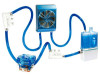
GIGABYTE™ blue eye and chipset waterblock Please make sure to turn off PC power before installation. 7-1 Remove the caps and tube clips from PCI slot and be careful to avoid the leakage. For the tube on 4-way splitter valve(1) and connect ... other side with the outlet of the tube with the second splitter on at this step until all the coolant drifts out. 7. 4-way Splitter Valve Instruction and User Manual (Adding VGA waterblock and chipset waterblock without disassembly) Ex. connect one side of VGA Blue Eye and fasten the tube clips. 22 Do not...
GIGABYTE™ blue eye and chipset waterblock Please make sure to turn off PC power before installation. 7-1 Remove the caps and tube clips from PCI slot and be careful to avoid the leakage. For the tube on 4-way splitter valve(1) and connect ... other side with the outlet of the tube with the second splitter on at this step until all the coolant drifts out. 7. 4-way Splitter Valve Instruction and User Manual (Adding VGA waterblock and chipset waterblock without disassembly) Ex. connect one side of VGA Blue Eye and fasten the tube clips. 22 Do not...

User Manual
Page 23
... on the power, please make sure to switch off 4-way splitter valve, turn off the power and keep all the devices away from any electronic part. 23 connect one side of chipset waterblock and fasten the tube clips. 7-5 Cut a tube into suitable size; Figure a Figure c Figure b Figure d 7-7 To accomplish liquid cooling...
... on the power, please make sure to switch off 4-way splitter valve, turn off the power and keep all the devices away from any electronic part. 23 connect one side of chipset waterblock and fasten the tube clips. 7-5 Cut a tube into suitable size; Figure a Figure c Figure b Figure d 7-7 To accomplish liquid cooling...