
Installation Guide
Page 2
English Table of Content Checklist...3 Specification...4 Feature...4 Warranty Item...5 Precautions...5 Installation Instructions for Fan Control Box & Power Cable 6 Power Installation and 3.5" Fan Speed Controller Installation 7 Power Installation and PCI Fan Speed Controller Installation 8 Installation Instructions for P4 LGA775RM & Cooler 9 Installation Instructions for Intel® Pentium® 4 mPGA478 Clips 10 Installation Instructions for AMD K8 (939 / 754) Clip 11 Installation Instructions for AMD K7 Clip 12 GH-PDU21-MF - 2 -
English Table of Content Checklist...3 Specification...4 Feature...4 Warranty Item...5 Precautions...5 Installation Instructions for Fan Control Box & Power Cable 6 Power Installation and 3.5" Fan Speed Controller Installation 7 Power Installation and PCI Fan Speed Controller Installation 8 Installation Instructions for P4 LGA775RM & Cooler 9 Installation Instructions for Intel® Pentium® 4 mPGA478 Clips 10 Installation Instructions for AMD K8 (939 / 754) Clip 11 Installation Instructions for AMD K7 Clip 12 GH-PDU21-MF - 2 -

Installation Guide
Page 3
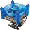
GH-PDU21-MF English Checklist (1)GH-PDU21 -MF Cooler (2)LGA775 RM (3) P4 clips (4) K8 clip (5) K7 clip (6) Heat sink paste (7)Screw (8) Fan control box (9)Speed control (10)Powercable & 3.5" bracket (11) PCI bracket (12)GH-PDU21-MF (13) Double-sided user's manual adhesive strip (note1) The double-sided adhesive strip is to attach the fan control box to the chassis. - 3 -
GH-PDU21-MF English Checklist (1)GH-PDU21 -MF Cooler (2)LGA775 RM (3) P4 clips (4) K8 clip (5) K7 clip (6) Heat sink paste (7)Screw (8) Fan control box (9)Speed control (10)Powercable & 3.5" bracket (11) PCI bracket (12)GH-PDU21-MF (13) Double-sided user's manual adhesive strip (note1) The double-sided adhesive strip is to attach the fan control box to the chassis. - 3 -

Installation Guide
Page 4
English Specification y Heat Sink Dimension : 110x110 x 109mm y Heatpipe Number : 4 y Fan Speed : 1,700~3,200 rpm y Rated Voltage : 12V y Noise :21.3 ~ 40.1... 478 3.4GHz AMD AthlonTM FX55 / AMD AthlonTM XP 4000+ AMD K7 3200+ y Unique and patented cooler bracket design for both 3.5" front panel and PCI rear panel y Easy clip installation - directional cooler design y Linear fan speed control module, suitable for Intel® Pentium®4 LGA775 / mPGA 478...200 rpm) y Unique fan frame design sustained by 4 artistic pillars y Brilliant Blue LEDS y Omni- No tool required GH-PDU21-MF - 4 -
English Specification y Heat Sink Dimension : 110x110 x 109mm y Heatpipe Number : 4 y Fan Speed : 1,700~3,200 rpm y Rated Voltage : 12V y Noise :21.3 ~ 40.1... 478 3.4GHz AMD AthlonTM FX55 / AMD AthlonTM XP 4000+ AMD K7 3200+ y Unique and patented cooler bracket design for both 3.5" front panel and PCI rear panel y Easy clip installation - directional cooler design y Linear fan speed control module, suitable for Intel® Pentium®4 LGA775 / mPGA 478...200 rpm) y Unique fan frame design sustained by 4 artistic pillars y Brilliant Blue LEDS y Omni- No tool required GH-PDU21-MF - 4 -

Installation Guide
Page 5
...Please refer to the motherboard BIOS to installation. Read the user's manual before computer transport to prevent damage to the cooler itself as well as prevent problems during installtion. - 5 - Please make sure the computer is foolproof. overclocking) Inability to install the product as a result of other... bottom protective layer of the cooler exceeding normal standards, please remove the cooler before use beyond the advised standards (eg. Each connector on the fan control box is turned off and its power disconnected prior to verify actual fan speed levels. GH-PDU21-MF
...Please refer to the motherboard BIOS to installation. Read the user's manual before computer transport to prevent damage to the cooler itself as well as prevent problems during installtion. - 5 - Please make sure the computer is foolproof. overclocking) Inability to install the product as a result of other... bottom protective layer of the cooler exceeding normal standards, please remove the cooler before use beyond the advised standards (eg. Each connector on the fan control box is turned off and its power disconnected prior to verify actual fan speed levels. GH-PDU21-MF

Installation Guide
Page 6
English Installation Instructions for Fan Control Box & Power Cable Connector for Cooler GH-PDU21-MF - 6 - Connect the other end of the power cable to the 3-pin CPU fan header on the motherboard. (LGA775) Power connector for 3.5 Fan Speed controller Power Cable connector Fan Control Box o r Connect the other end of the power cable to the 4-pin CPU fan header on the motherboard.
English Installation Instructions for Fan Control Box & Power Cable Connector for Cooler GH-PDU21-MF - 6 - Connect the other end of the power cable to the 3-pin CPU fan header on the motherboard. (LGA775) Power connector for 3.5 Fan Speed controller Power Cable connector Fan Control Box o r Connect the other end of the power cable to the 4-pin CPU fan header on the motherboard.

Installation Guide
Page 7
...box (Figure 2-1). GH-PDU21-MF English Power Installation and 3.5" Fan Speed Controller Installation Figure 1 Securely hold the 3.5" fan speed controller bracket in place with the GH-PDU21-MF cooler is completed . (...Figure 4-2). - 7 - Figure 3-1 Figure 4-1 Figure 4-2 Figure 3 Connect the power cable connector of the power cable included with the screws provided(Figure 1-1). Then the installation... is connected to the fan control box (Figure 3-1). Figure 4 Assure that one end of the cooler to the fan ...
...box (Figure 2-1). GH-PDU21-MF English Power Installation and 3.5" Fan Speed Controller Installation Figure 1 Securely hold the 3.5" fan speed controller bracket in place with the GH-PDU21-MF cooler is completed . (...Figure 4-2). - 7 - Figure 3-1 Figure 4-1 Figure 4-2 Figure 3 Connect the power cable connector of the power cable included with the screws provided(Figure 1-1). Then the installation... is connected to the fan control box (Figure 3-1). Figure 4 Assure that one end of the cooler to the fan ...

Installation Guide
Page 8
Figure 3-1 Figure 3 Repeat the steps in sequence. English Power Installation and PCI Fan Speed Controller Installation Figure 1-1 Figure 1-2 Figure 2-1 Figure 1 Disassemble the turn knob, bolt and fan speed controller from the 3.5" bracket and reassemble these parts onto a PCI bracket in "Power Installation and 3.5" Fan Speed Controller Installation (Figure 2-1~Figure 4-2)". Use screws to secure the PCI bracket in the selected PCI slot. GH-PDU21-MF - 8 - Figure 2 Place the PCI bracket with the fan speed controller in place. The installation is now completed.
Figure 3-1 Figure 3 Repeat the steps in sequence. English Power Installation and PCI Fan Speed Controller Installation Figure 1-1 Figure 1-2 Figure 2-1 Figure 1 Disassemble the turn knob, bolt and fan speed controller from the 3.5" bracket and reassemble these parts onto a PCI bracket in "Power Installation and 3.5" Fan Speed Controller Installation (Figure 2-1~Figure 4-2)". Use screws to secure the PCI bracket in the selected PCI slot. GH-PDU21-MF - 8 - Figure 2 Place the PCI bracket with the fan speed controller in place. The installation is now completed.

Installation Guide
Page 9
... surface of the CPU. GH-PDU21-MF Figure 1 Place the LGA775RM onto the LGA775 motherboard so that side A is parallel with CAM. GH-PDU21-MF provides manual fan speed control function. English Installation Instructions for Intel® Pentium®4 mPGA478 Clips" - 9 - Please add an adequate layer of heat sink paste on the cooler unit to "Installation Instructions for P4 LGA775RM & Cooler Side A Side B ARM...
... surface of the CPU. GH-PDU21-MF Figure 1 Place the LGA775RM onto the LGA775 motherboard so that side A is parallel with CAM. GH-PDU21-MF provides manual fan speed control function. English Installation Instructions for Intel® Pentium®4 mPGA478 Clips" - 9 - Please add an adequate layer of heat sink paste on the cooler unit to "Installation Instructions for P4 LGA775RM & Cooler Side A Side B ARM...

Installation Guide
Page 10
GH-PDU21-MF - 10 - Figure 1-2 showing the correct installation of the CPU(Figure1-1). Part B: Tightly contact the cooler bracket. Assure that Part C is now completed. English Installation Instructions for Intel® Pentium® 4 mPGA478 Clips Figure 1-1 Figure 1-2 C BA Figure 2 Figure 1 Please add an adequate layer of heat sink paste on the same side as the heat pipes. Part C: Secured to the retention...
GH-PDU21-MF - 10 - Figure 1-2 showing the correct installation of the CPU(Figure1-1). Part B: Tightly contact the cooler bracket. Assure that Part C is now completed. English Installation Instructions for Intel® Pentium® 4 mPGA478 Clips Figure 1-1 Figure 1-2 C BA Figure 2 Figure 1 Please add an adequate layer of heat sink paste on the same side as the heat pipes. Part C: Secured to the retention...

Installation Guide
Page 11
... Installation Instructions for AMD K8 (939 / 754) Clip Figure 1-1 Figure 1-2 Figure 2 Figure 3 Figure 4-1 Figure 4-2 Figure 1 Please add an adequate layer of heat sink paste on the CPU socket and then push firmly downwards to secure the cooler atop the CPU. The installation is now completed. - 11 - Repeat the steps in space. GH-PDU21-MF Figure 2 Figure showing the correct installation...
... Installation Instructions for AMD K8 (939 / 754) Clip Figure 1-1 Figure 1-2 Figure 2 Figure 3 Figure 4-1 Figure 4-2 Figure 1 Please add an adequate layer of heat sink paste on the CPU socket and then push firmly downwards to secure the cooler atop the CPU. The installation is now completed. - 11 - Repeat the steps in space. GH-PDU21-MF Figure 2 Figure showing the correct installation...

Installation Guide
Page 12
... (Figure2-1)on the surface of the CPU. GH-PDU21-MF - 12 - English Installation Instructions for AMD K7 Clip Figure 1-1 A Figure 1-2 B Figure 1-3 Figure 2-1 Figure 2-2 Figure 2-3 Figure 3 Figure 1 Please add an adequate layer of heat sink paste on point B at the bottom of the cooler (Figure 2-2) and push down on the...until it's firmly locked. Figure 3 Align the three spaces on the cooler with the three clips on the base of the CPU and make sure point A of the clip (Figure 2-1) is now completed. The installation is placed on point B at the bottom of the arrow (Figure ...
... (Figure2-1)on the surface of the CPU. GH-PDU21-MF - 12 - English Installation Instructions for AMD K7 Clip Figure 1-1 A Figure 1-2 B Figure 1-3 Figure 2-1 Figure 2-2 Figure 2-3 Figure 3 Figure 1 Please add an adequate layer of heat sink paste on point B at the bottom of the cooler (Figure 2-2) and push down on the...until it's firmly locked. Figure 3 Align the three spaces on the cooler with the three clips on the base of the CPU and make sure point A of the clip (Figure 2-1) is now completed. The installation is placed on point B at the bottom of the arrow (Figure ...

Installation Guide
Page 16
y : 110 x 110 x 109 mm y : 4 y : 1,700 ~ 3,200 rpm y : 12V y : 21.3 ~40.1 dBA y : Ball Bearing y : y : Aluminum y : 0.1~ 0.5 y : 36.2 ~ 68.5 CFM y : 50,000 hr y : 430g y : Intel® Pentium® 4 LGA775 840 / 670 / 570(3.8GHz) Intel® Pentium® 4 478 3.4GHz AMD AthlonTM FX55 / AMD AthlonTM XP 4000+ AMD K7 3200+ y y y 4 y y y LED y y y GH-PDU21-MF P4 LGA775 P4 mPGA478 AMDK8(939 / 754) AMDK7 (1,700~3,200 rpm) 3.5 PCI - 16 -
y : 110 x 110 x 109 mm y : 4 y : 1,700 ~ 3,200 rpm y : 12V y : 21.3 ~40.1 dBA y : Ball Bearing y : y : Aluminum y : 0.1~ 0.5 y : 36.2 ~ 68.5 CFM y : 50,000 hr y : 430g y : Intel® Pentium® 4 LGA775 840 / 670 / 570(3.8GHz) Intel® Pentium® 4 478 3.4GHz AMD AthlonTM FX55 / AMD AthlonTM XP 4000+ AMD K7 3200+ y y y 4 y y y LED y y y GH-PDU21-MF P4 LGA775 P4 mPGA478 AMDK8(939 / 754) AMDK7 (1,700~3,200 rpm) 3.5 PCI - 16 -
