
User Manual
Page 1
GIGABYTE ODIN Power Supply User's Manual ATX 12V version 2.2 power supply Products: ODIN GT / ODIN PRO Models: GE-S800A-D1, GE-S680A-D1, GE-S550A-D1 / GE-M800A-D1, GE-M680A-D1, GE-M550A-D1 Specifications are registered trademarks of their respective companies All brand names and products are subject to change without notice.
GIGABYTE ODIN Power Supply User's Manual ATX 12V version 2.2 power supply Products: ODIN GT / ODIN PRO Models: GE-S800A-D1, GE-S680A-D1, GE-S550A-D1 / GE-M800A-D1, GE-M680A-D1, GE-M550A-D1 Specifications are registered trademarks of their respective companies All brand names and products are subject to change without notice.
User Manual
Page 2
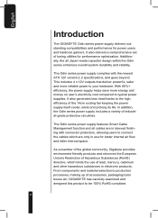
.../color boxes etc; GIGABYTE has carefully examined and designed this product to your hardware. As a member of the global community, Gigabyte provides environment friendly products and observes the European Union's Restriction of lead, mercury, cadmium and other hazardous substances in sleeved finishing with the newest ATX 12V version 2.2 specifications, and goes beyond. With 80%+ efficiency, the power supply...
.../color boxes etc; GIGABYTE has carefully examined and designed this product to your hardware. As a member of the global community, Gigabyte provides environment friendly products and observes the European Union's Restriction of lead, mercury, cadmium and other hazardous substances in sleeved finishing with the newest ATX 12V version 2.2 specifications, and goes beyond. With 80%+ efficiency, the power supply...

User Manual
Page 3
... open this power supply unit! No modification to follow the installation process within the user manual. Caution! The product's warranty label has been removed or damaged. 8.The devices inside ! earthquake, lightning, fire, and floods. 7. No serviceable components inside , including power supply, hard disk, CD-ROM drive, motherboard, ventilator, etc, are not covered by failure to this power supply unit! Incorrect connector installation may possible...
... open this power supply unit! No modification to follow the installation process within the user manual. Caution! The product's warranty label has been removed or damaged. 8.The devices inside ! earthquake, lightning, fire, and floods. 7. No serviceable components inside , including power supply, hard disk, CD-ROM drive, motherboard, ventilator, etc, are not covered by failure to this power supply unit! Incorrect connector installation may possible...

User Manual
Page 4
Recommended HDD Space: 30Mb 4. Windows 2000\ XP\ Vista 2. Recommended RAM: 512mb RAM 5. Recommended display resolution: >1024 x 768 Power Supply Unit 1 Fixing Screws 4 System fan speed control and power cable (ODIN GT only) 1 Thermal sensor cable (ODIN GT only) 4 USB Converter (ODIN GT only) 1 PCI-E (Red) power cable 1 PCI-E (Blue) power cable (800W & 680W only) 1 Peripheral power with FDD connector cable 1 S-ATA power cable 2 Peripheral power cable 1 CD (ODIN GT only) 1 4 CD -Rom 3. English System Requirement 1.
Recommended HDD Space: 30Mb 4. Windows 2000\ XP\ Vista 2. Recommended RAM: 512mb RAM 5. Recommended display resolution: >1024 x 768 Power Supply Unit 1 Fixing Screws 4 System fan speed control and power cable (ODIN GT only) 1 Thermal sensor cable (ODIN GT only) 4 USB Converter (ODIN GT only) 1 PCI-E (Red) power cable 1 PCI-E (Blue) power cable (800W & 680W only) 1 Peripheral power with FDD connector cable 1 S-ATA power cable 2 Peripheral power cable 1 CD (ODIN GT only) 1 4 CD -Rom 3. English System Requirement 1.

User Manual
Page 6
PCI-E 1 cable management Red d. LED light switch (For Odin Pro only) 6 AC power switch c. English 1. PCI-E 2 cable management Blue e. 12V, 5V, 3.3V peripheral power cable management f. Fan speed control power cable management (For Odin GT only) h. Power Supply 1-1.Power Supply Unit a b f d g c h e a. Thermal sensor cable management (For Odin GT only) g. AC In b.
PCI-E 1 cable management Red d. LED light switch (For Odin Pro only) 6 AC power switch c. English 1. PCI-E 2 cable management Blue e. 12V, 5V, 3.3V peripheral power cable management f. Fan speed control power cable management (For Odin GT only) h. Power Supply 1-1.Power Supply Unit a b f d g c h e a. Thermal sensor cable management (For Odin GT only) g. AC In b.

User Manual
Page 7
English 1-2.Power Supply Cables a. 24-pin main power connector b. 8-pin +12V CPU power connector c. 4-pin +12V CPU power connector d. 6-pin PCI-E power connector (for 550W only one PCI-E connector) e. Smart cable management Peripheral power cable h. Smart cable management Thermal sensor cable (For Odin GT only) k. Peripheral power with FDD connector cable i. Smart cable management PCI-E (Red and Blue) power cable g. Smart cable management S-ATA power cable j. USB Data connector (For Odin GT only) f. Smart cable management System fan speed control and power cable (For Odin GT only...
English 1-2.Power Supply Cables a. 24-pin main power connector b. 8-pin +12V CPU power connector c. 4-pin +12V CPU power connector d. 6-pin PCI-E power connector (for 550W only one PCI-E connector) e. Smart cable management Peripheral power cable h. Smart cable management Thermal sensor cable (For Odin GT only) k. Peripheral power with FDD connector cable i. Smart cable management PCI-E (Red and Blue) power cable g. Smart cable management S-ATA power cable j. USB Data connector (For Odin GT only) f. Smart cable management System fan speed control and power cable (For Odin GT only...

User Manual
Page 8
ent 12V rails) 18AWG (Wire) Black Black Black Signal COM COM COM Pin Pin Signal 4 1 12V1DC 5 2 12V1DC 6 3 12V1DC 18AWG (Wire) Yellow Yellow Yellow 1-3-4. nector to PSU (There are Red and Blue connectors for differ- English 1-3.Power Supply Connectors 1-3-1. 24-PIN Main Power Connector 18AWG (Wire) Orange Blue Black Green (22AWG) Black Black Black Red Red Red Black Signal +3.3Vdc -12Vdc COM PS-ON COM...
ent 12V rails) 18AWG (Wire) Black Black Black Signal COM COM COM Pin Pin Signal 4 1 12V1DC 5 2 12V1DC 6 3 12V1DC 18AWG (Wire) Yellow Yellow Yellow 1-3-4. nector to PSU (There are Red and Blue connectors for differ- English 1-3.Power Supply Connectors 1-3-1. 24-PIN Main Power Connector 18AWG (Wire) Orange Blue Black Green (22AWG) Black Black Black Red Red Red Black Signal +3.3Vdc -12Vdc COM PS-ON COM...
User Manual
Page 9
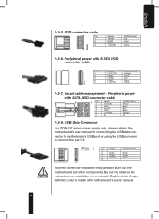
... HDD connector cable Pin Signal 1 +12 VDC 2 COM 3 +5VDC 4 COM 5 +3.3VDC 6 NC 18AWG (Wire) Yellow Black Red Black Orange NC 1-3-8. USB Data Connector For ODIN GT series power supply only, please refer to the motherboard's user manual for connecting the USB data connector to motherboard's USB port or using the USB converter to observe the instructions on installation in the manual. Pin Signal 1 2 Data - 3 Data + 4 Ground 5 20AWG (Wire) White Green Black Incorrect connector installation may...
... HDD connector cable Pin Signal 1 +12 VDC 2 COM 3 +5VDC 4 COM 5 +3.3VDC 6 NC 18AWG (Wire) Yellow Black Red Black Orange NC 1-3-8. USB Data Connector For ODIN GT series power supply only, please refer to the motherboard's user manual for connecting the USB data connector to motherboard's USB port or using the USB converter to observe the instructions on installation in the manual. Pin Signal 1 2 Data - 3 Data + 4 Ground 5 20AWG (Wire) White Green Black Incorrect connector installation may...
User Manual
Page 10
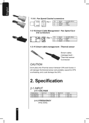
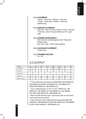
... cable management Thermal sensor Connector CAUTION Don't place the Thermal sensor between CPU and Cooler; Specification 2-1 INPUT 2-1-1 VOLTAGE Model Name GE-S800A-D1 GE-S680A-D1 GE-S550A-D1 Minimum 90 90 90 Nominal 115~230 115~230 115~230 2-1-2 FREQUENCY 47Hz~63Hz Maximum 264 264 264 Units VAC rms VAC rms VAC rms 10 Fan Speed Control connectors Pin Signal 24 AWG (Wire...
... cable management Thermal sensor Connector CAUTION Don't place the Thermal sensor between CPU and Cooler; Specification 2-1 INPUT 2-1-1 VOLTAGE Model Name GE-S800A-D1 GE-S680A-D1 GE-S550A-D1 Minimum 90 90 90 Nominal 115~230 115~230 115~230 2-1-2 FREQUENCY 47Hz~63Hz Maximum 264 264 264 Units VAC rms VAC rms VAC rms 10 Fan Speed Control connectors Pin Signal 24 AWG (Wire...
User Manual
Page 11
GE-M680A-D1)/ 550W (GE-S550A-D1; The Combined power of +5V +3.3V is 800W MAX (GE-S800A-D1; GE-M550A-D1) - Peak currents may last up to 12 seconds with no more than one occurrence per minute. - GE-M550A-D1) - GE-S680A-D1; GE-M800A-D1; GE-M800A-D1)/680W (GE-S680A-D1; Total combined +12V output load not exceeding 62A (GES800A-D1; GE-M800A-D1)/52A (GE-S680A-D1; when AC input 115Vac at full load (typical...
GE-M680A-D1)/ 550W (GE-S550A-D1; The Combined power of +5V +3.3V is 800W MAX (GE-S800A-D1; GE-M550A-D1) - Peak currents may last up to 12 seconds with no more than one occurrence per minute. - GE-M550A-D1) - GE-S680A-D1; GE-M800A-D1; GE-M800A-D1)/680W (GE-S680A-D1; Total combined +12V output load not exceeding 62A (GES800A-D1; GE-M800A-D1)/52A (GE-S680A-D1; when AC input 115Vac at full load (typical...

User Manual
Page 12
... +5V 1000uF 2-8 TRANSIENT OVERSHOOT Step load changes of up to 50% of full load at 230Vac input 2-5 POWER GOOD DELAY 100-500 msec 2-6 POWER FAIL DELAY >1msec. 2-7 TURN-ON DELAY TIME 2000 msec max. The DC output voltage will stay within the rating. TTL Low/PS-ON VIL = 0.8V max, IIL = -1.6mAmax@Vin=0.4V...
... +5V 1000uF 2-8 TRANSIENT OVERSHOOT Step load changes of up to 50% of full load at 230Vac input 2-5 POWER GOOD DELAY 100-500 msec 2-6 POWER FAIL DELAY >1msec. 2-7 TURN-ON DELAY TIME 2000 msec max. The DC output voltage will stay within the rating. TTL Low/PS-ON VIL = 0.8V max, IIL = -1.6mAmax@Vin=0.4V...
User Manual
Page 13
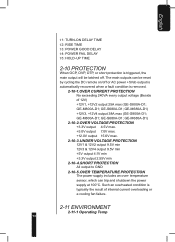
... on/off . GE-M680A-D1) +12V3, +12V4 output 38A max (GE-S800A-D1; Such an overheated condition is removed. 2-10-1.OVER CURRENT PROTECTION No exceeding 240VA every output voltage (Beside of internal current overloading or a cooling fan failure. 2-11 ENVIRONMENT 2-11-1 Operating Temp 13 GE-S680A-D1; The main outputs can trip and shutdown the power supply at 100°C. GE-M680A-D1) 2-10-2.OVER...
... on/off . GE-M680A-D1) +12V3, +12V4 output 38A max (GE-S800A-D1; Such an overheated condition is removed. 2-10-1.OVER CURRENT PROTECTION No exceeding 240VA every output voltage (Beside of internal current overloading or a cooling fan failure. 2-11 ENVIRONMENT 2-11-1 Operating Temp 13 GE-S680A-D1; The main outputs can trip and shutdown the power supply at 100°C. GE-M680A-D1) 2-10-2.OVER...

User Manual
Page 15
.... Connect the 4 / 8-pin 12V CPU power connector to the motherboard and the peripheral devices such as needed . 8. Disconnect the power cord from the power supply to your computer case 6. Note: Please refer to Section 4) 1. When there is a need for usage details. 15 Switch off the system. 2. Disconnect all the power connectors from your PCI express graphic card's user manual for PCI-E power, please use Smart Cable management...
.... Connect the 4 / 8-pin 12V CPU power connector to the motherboard and the peripheral devices such as needed . 8. Disconnect the power cord from the power supply to your computer case 6. Note: Please refer to Section 4) 1. When there is a need for usage details. 15 Switch off the system. 2. Disconnect all the power connectors from your PCI express graphic card's user manual for PCI-E power, please use Smart Cable management...

User Manual
Page 16
Thermal Sensor cable, use Smart Cable Management power connectors. 11. CAUTION: Do not connect to monitor the temperature. it will damage the thermal sensor and CPU. (Odin GT series only) 16 Connect Smart Cable Management - With a Smart Cable Management -Fan speed control power connector, users may connect two 3-pin system fans. It can be used in high temperature environment. This allows Odin GT power supply to monitor and control the...
Thermal Sensor cable, use Smart Cable Management power connectors. 11. CAUTION: Do not connect to monitor the temperature. it will damage the thermal sensor and CPU. (Odin GT series only) 16 Connect Smart Cable Management - With a Smart Cable Management -Fan speed control power connector, users may connect two 3-pin system fans. It can be used in high temperature environment. This allows Odin GT power supply to monitor and control the...
User Manual
Page 17
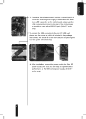
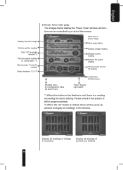
... rear slot. (Odin GT series only) 14. If there is no USB connector on the motherboard, please use the USB converter to connect to the rear of the Odin series power supply. (Odin GT series only) 17 After installation, connect the power cord to experience the performance of the motherboard or an add-on card with a USB I/O port. (Odin GT series...
... rear slot. (Odin GT series only) 14. If there is no USB connector on the motherboard, please use the USB converter to connect to the rear of the Odin series power supply. (Odin GT series only) 17 After installation, connect the power cord to experience the performance of the motherboard or an add-on card with a USB I/O port. (Odin GT series...
User Manual
Page 18
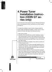
... the system to monitor and adjust the hardware function. 1. Power Tuner Installation Instruction (ODIN GT series only) For the first time of P-Tuner shown as left. (It's possible that a new hardware is found, and there is not a problem; If it 's simply an improvement. Start up by step. 4. Follow the instruction and install Power Tuner into the "start up" folder in...
... the system to monitor and adjust the hardware function. 1. Power Tuner Installation Instruction (ODIN GT series only) For the first time of P-Tuner shown as left. (It's possible that a new hardware is found, and there is not a problem; If it 's simply an improvement. Start up by step. 4. Follow the instruction and install Power Tuner into the "start up" folder in...
User Manual
Page 19
... menu (A) Alarm menu Power Supply Light switch *1 When the button or fan flashes in centre flash, *1) Thermometer T1 and T3 reading Switch between °C & °F 6. all function can be a pop up window to get the reading Click "all" for single window *2 PSU fan speed reading (in red, there is a reading exceeding the alarm setting. Display all readings...
... menu (A) Alarm menu Power Supply Light switch *1 When the button or fan flashes in centre flash, *1) Thermometer T1 and T3 reading Switch between °C & °F 6. all function can be a pop up window to get the reading Click "all" for single window *2 PSU fan speed reading (in red, there is a reading exceeding the alarm setting. Display all readings...
User Manual
Page 20
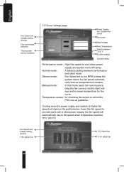
... PSU use mouse to provide users with a silent power supply; Manual mode: In this mode users can use as temperature increases. the fan speed will improve the performance, lower the fan speed to drag the fan curve or set ...Fan Speed and voltage setting window +12V adjust bar +5V Adjust bar -3.3V adjust bar 20 English Fan speed and voltage setting window Fan curve mode selection Thermometer sensor selection 7. Temperature sensor: for fan curve. cally rises as guideline. P-Tuner Voltage page Power Supply fan / System fan switch Fan curve Start Voltage Start Temperature Switch...
... PSU use mouse to provide users with a silent power supply; Manual mode: In this mode users can use as temperature increases. the fan speed will improve the performance, lower the fan speed to drag the fan curve or set ...Fan Speed and voltage setting window +12V adjust bar +5V Adjust bar -3.3V adjust bar 20 English Fan speed and voltage setting window Fan curve mode selection Thermometer sensor selection 7. Temperature sensor: for fan curve. cally rises as guideline. P-Tuner Voltage page Power Supply fan / System fan switch Fan curve Start Voltage Start Temperature Switch...
User Manual
Page 21
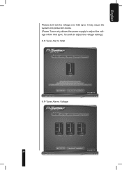
P-Tuner Alarm: Watt 9. It may cause the system into protection mode. (Power Tuner only allows the power supply to adjust the voltage setting.) 8. It is safe to adjust the voltage within Intel spec. P-Tuner Alarm: Voltage 21 English Please don't set the voltage over Intel spec.
P-Tuner Alarm: Watt 9. It may cause the system into protection mode. (Power Tuner only allows the power supply to adjust the voltage setting.) 8. It is safe to adjust the voltage within Intel spec. P-Tuner Alarm: Voltage 21 English Please don't set the voltage over Intel spec.
User Manual
Page 23
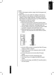
... up failure to another computer. Disconnect all the power connectors from the power supply to motherboard, and the peripheral devices such as in the computer, which the USB cable connects to start ODIN GT power supply. Use the USB converter to connect the Odin GT power supply to recover the system. h. When there is an error within the settings, it . 2. Remove the AC power cord. b. Short the connector as...
... up failure to another computer. Disconnect all the power connectors from the power supply to motherboard, and the peripheral devices such as in the computer, which the USB cable connects to start ODIN GT power supply. Use the USB converter to connect the Odin GT power supply to recover the system. h. When there is an error within the settings, it . 2. Remove the AC power cord. b. Short the connector as...
