Manual
Page 3
...their respective owners. Disclaimer Information in this manual may be reproduced, copied, translated, transmitted, or published in the use of GIGABYTE. Example: The trademarks mentioned in this : "REV: X.X." Check your motherboard looks like this manual are legally registered to .... For product-related information, check on our website at: http://www.gigabyte.com Identifying Your Motherboard Revision The revision number on your motherboard revision before updating motherboard BIOS, drivers, or when looking for technical information. All rights reserved. For example, ...
...their respective owners. Disclaimer Information in this manual may be reproduced, copied, translated, transmitted, or published in the use of GIGABYTE. Example: The trademarks mentioned in this : "REV: X.X." Check your motherboard looks like this manual are legally registered to .... For product-related information, check on our website at: http://www.gigabyte.com Identifying Your Motherboard Revision The revision number on your motherboard revision before updating motherboard BIOS, drivers, or when looking for technical information. All rights reserved. For example, ...
Manual
Page 4
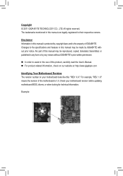
Table of Contents GA-Q67M-D2H-B3 Motherboard Layout 5 GA-Q67M-D2H-B3 Motherboard Block Diagram 6 Chapter 1 Hardware Installation 7 1-1 Installation Precautions 7 1-2 Product Specifications 8 1-3 Installing the CPU and CPU Cooler 10 1-4 Installing the Memory 11 1-5 Installing an Expansion Card 11 1-6 Back Panel Connectors 12 1-7 Internal Connectors 14 Chapter 2 BIOS Setup 23 2-1 The POST screen 23 2-2 The Main Menu 23 2-3 Advanced...24...
Table of Contents GA-Q67M-D2H-B3 Motherboard Layout 5 GA-Q67M-D2H-B3 Motherboard Block Diagram 6 Chapter 1 Hardware Installation 7 1-1 Installation Precautions 7 1-2 Product Specifications 8 1-3 Installing the CPU and CPU Cooler 10 1-4 Installing the Memory 11 1-5 Installing an Expansion Card 11 1-6 Back Panel Connectors 12 1-7 Internal Connectors 14 Chapter 2 BIOS Setup 23 2-1 The POST screen 23 2-2 The Main Menu 23 2-3 Advanced...24...
Manual
Page 5
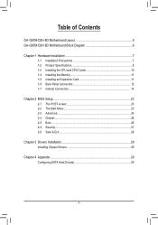
... DP_HDMI_SPDIF Level Shifter R_USB USB_LAN SYS_FAN LGA1155 ATX LPT AUDIO BAT PCIEX16 CPU_FAN GA-Q67M-D2H-B3 PCI1 Intel 82579 PCI2 PCIEX4 SPDIF_O CODEC Intel® Q67 BIOS CLR_CMOS iTE IT8728 SATA3_0 SATA3_1 SATA2_2 SATA2_3 SATA2_4 SATA2_5 DEBUG_PORT F_AUDIO F_USB4 F_USB3 ...F_USB2 F_USB1 F_PANEL COMA COMB Box Contents GA-Q67M-D2H-B3 motherboard Motherboard driver disk User's Manual Two SATA cables ...
... DP_HDMI_SPDIF Level Shifter R_USB USB_LAN SYS_FAN LGA1155 ATX LPT AUDIO BAT PCIEX16 CPU_FAN GA-Q67M-D2H-B3 PCI1 Intel 82579 PCI2 PCIEX4 SPDIF_O CODEC Intel® Q67 BIOS CLR_CMOS iTE IT8728 SATA3_0 SATA3_1 SATA2_2 SATA2_3 SATA2_4 SATA2_5 DEBUG_PORT F_AUDIO F_USB4 F_USB3 ...F_USB2 F_USB1 F_PANEL COMA COMB Box Contents GA-Q67M-D2H-B3 motherboard Motherboard driver disk User's Manual Two SATA cables ...
Manual
Page 6
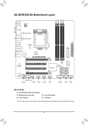
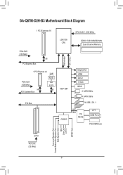
GA-Q67M-D2H-B3 Motherboard Block Diagram 1 PCI Express x16 CPU CLK+/- (100 MHz) PCIe CLK (100 MHz) x16 PCI Express Bus 1 PCI Express x4 LAN RJ45 PCIe CLK (100 MHz) Intel 82579 x4 x1 PCI Express Bus PCI Bus LGA1155 CPU DDR3 1333/1066/800 MHz Dual Channel Memory DMI Interface FDI Interface Intel® Q67 DisplayPort HDMI DVI-D D-Sub BIOS 2 SATA 6Gb/s 4 SATA 3Gb/s 14 USB 2.0/1.1 CODEC LPC Bus iTE IT8728 LPT COM Ports PS/2 KB/Mouse Surround Speaker Out Center/Subwoofer Speaker Out Side Speaker Out MIC Line Out Line In S/PDIF Out 2 PCI PCI CLK (33 MHz) - 6 -
GA-Q67M-D2H-B3 Motherboard Block Diagram 1 PCI Express x16 CPU CLK+/- (100 MHz) PCIe CLK (100 MHz) x16 PCI Express Bus 1 PCI Express x4 LAN RJ45 PCIe CLK (100 MHz) Intel 82579 x4 x1 PCI Express Bus PCI Bus LGA1155 CPU DDR3 1333/1066/800 MHz Dual Channel Memory DMI Interface FDI Interface Intel® Q67 DisplayPort HDMI DVI-D D-Sub BIOS 2 SATA 6Gb/s 4 SATA 3Gb/s 14 USB 2.0/1.1 CODEC LPC Bus iTE IT8728 LPT COM Ports PS/2 KB/Mouse Surround Speaker Out Center/Subwoofer Speaker Out Side Speaker Out MIC Line Out Line In S/PDIF Out 2 PCI PCI CLK (33 MHz) - 6 -
Manual
Page 9
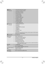
...; 1 x 64 Mbit flash ŠŠ Use of licensed AMI BIOS ŠŠ PnP 1.0a, DMI 2.0, SM BIOS 2.4, ACPI 1.0b Unique Features ŠŠ Support for Xpress Install ŠŠ Support for Q-Share Bundled Software ŠŠ Norton Internet Security (OEM version) - 9 - Hardware ...
...; 1 x 64 Mbit flash ŠŠ Use of licensed AMI BIOS ŠŠ PnP 1.0a, DMI 2.0, SM BIOS 2.4, ACPI 1.0b Unique Features ŠŠ Support for Xpress Install ŠŠ Support for Q-Share Bundled Software ŠŠ Norton Internet Security (OEM version) - 9 - Hardware ...
Manual
Page 11
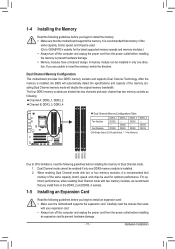
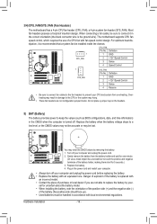
... recommend that memory of the memory. After the memory is recommended that memory of the same capacity, brand, speed, and chips be used . (Go to GIGABYTE's website for optimum performance. Dual Channel mode cannot be installed in only one DDR3 memory module is recommended that you install them in Dual Channel... DDR3_4 Due to CPU limitations, read the manual that the motherboard supports the memory. DS/SS DS/SS DDR3_3 DS/SS - It is installed, the BIOS will double the original memory bandwidth.
... recommend that memory of the memory. After the memory is recommended that memory of the same capacity, brand, speed, and chips be used . (Go to GIGABYTE's website for optimum performance. Dual Channel mode cannot be installed in only one DDR3 memory module is recommended that you install them in Dual Channel... DDR3_4 Due to CPU limitations, read the manual that the motherboard supports the memory. DS/SS DS/SS DDR3_3 DS/SS - It is installed, the BIOS will double the original memory bandwidth.
Manual
Page 13
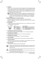
..., walkman, etc. Microphones must be reconfigured to connect front speakers in a 7.1-channel audio configuration. The following describes the states of 2560x1600p but not during the BIOS Setup or POST process. Use this audio jack for the Onboard Graphics: This motherboard provides four video output ports: D-Sub, DVI-D, HDMI, and DisplayPort. Line...
..., walkman, etc. Microphones must be reconfigured to connect front speakers in a 7.1-channel audio configuration. The following describes the states of 2560x1600p but not during the BIOS Setup or POST process. Use this audio jack for the Onboard Graphics: This motherboard provides four video output ports: D-Sub, DVI-D, HDMI, and DisplayPort. Line...
Manual
Page 16
... or the system may be lost. You may clear the CMOS values by your- Overheating may result in damage to keep the values (such as BIOS configurations, date, and time information) in the correct orientation (the black connector wire is turned off your computer and unplug the power cord before replacing...
... or the system may be lost. You may clear the CMOS values by your- Overheating may result in damage to keep the values (such as BIOS configurations, date, and time information) in the correct orientation (the black connector wire is turned off your computer and unplug the power cord before replacing...
Manual
Page 18
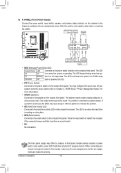
RESRES+ CICI+ PWR+ PWR- The LED is on when the hard drive is detected, the BIOS may issue beeps in different patterns to indicate the problem. •• HD (Hard Drive Activity LED) Connects to the reset switch on the chassis ... power switch on the chassis front panel. You may differ by issuing a beep code. When connecting your system using the power switch (refer to Chapter 2, "BIOS Setup," "Power Management Setup," for more information). •• SPEAK (Speaker): Connects to this header according to the power status indicator on the chassis front...
RESRES+ CICI+ PWR+ PWR- The LED is on when the hard drive is detected, the BIOS may issue beeps in different patterns to indicate the problem. •• HD (Hard Drive Activity LED) Connects to the reset switch on the chassis ... power switch on the chassis front panel. You may differ by issuing a beep code. When connecting your system using the power switch (refer to Chapter 2, "BIOS Setup," "Power Management Setup," for more information). •• SPEAK (Speaker): Connects to this header according to the power status indicator on the chassis front...
Manual
Page 19
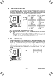
...-D2) 10 2 3 MIC2_R 4 -ACZ_DET 3 MIC Power 4 NC 5 LINE2_R 5 Line Out (R) 6 GND 6 NC 7 FAUDIO_JD 7 NC 8 No Pin 8 No Pin 9 LINE2_L 9 Line Out (L) 10 GND 10 NC BIOS Switcher (X58A-OC) DB_P•O•RTThe front panel audio header supports HD audio by expanDIP sion cards) for dPiCgIietaplowaeurdcoionnoecutotpr (uStATfrAo)(mX58yAo-OuCr )motherboard to...
...-D2) 10 2 3 MIC2_R 4 -ACZ_DET 3 MIC Power 4 NC 5 LINE2_R 5 Line Out (R) 6 GND 6 NC 7 FAUDIO_JD 7 NC 8 No Pin 8 No Pin 9 LINE2_L 9 Line Out (L) 10 GND 10 NC BIOS Switcher (X58A-OC) DB_P•O•RTThe front panel audio header supports HD audio by expanDIP sion cards) for dPiCgIietaplowaeurdcoionnoecutotpr (uStATfrAo)(mX58yAo-OuCr )motherboard to...
Manual
Page 22
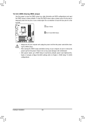
... short the two pins or use a metal object like a screwdriver to clear the CMOS values (e.g. date information and BIOS configurations) and reset the CMOS values to Chapter 2, "BIOS Setup," for a few seconds. Hardware Installation - 22 - Failure to do so may cause damage to the motherboard.... •• After system restart, go to BIOS Setup to load factory defaults (select Load Optimized Defaults) or manually configure the BIOS settings (refer to factory defaults. 15) CLR_CMOS (Clearing CMOS Jumper) Use this jumper to touch ...
... short the two pins or use a metal object like a screwdriver to clear the CMOS values (e.g. date information and BIOS configurations) and reset the CMOS values to Chapter 2, "BIOS Setup," for a few seconds. Hardware Installation - 22 - Failure to do so may cause damage to the motherboard.... •• After system restart, go to BIOS Setup to load factory defaults (select Load Optimized Defaults) or manually configure the BIOS settings (refer to factory defaults. 15) CLR_CMOS (Clearing CMOS Jumper) Use this jumper to touch ...
Manual
Page 23
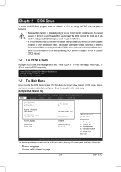
...to boot. Version 2.10.1208. Advanced Chipset Boot Security Save & Exit BIOS Information Project Name Project Version Memory Information Total Memory LAN MAC Information LAN MAC Address System Language System Date System Time Q67M-D2H-B3 F3 1024 MB (DDR3 1333) 888888888788 [English] [Wed 30/03/2011... CMOS jumper in system's failure to enter setup. 2-2 The Main Menu Once you enter the BIOS Setup program, the Main Menu (as shown below) appears on the BIOS information, Memory information, and LAN MAC information. If this occurs, try to clear the CMOS ...
...to boot. Version 2.10.1208. Advanced Chipset Boot Security Save & Exit BIOS Information Project Name Project Version Memory Information Total Memory LAN MAC Information LAN MAC Address System Language System Date System Time Q67M-D2H-B3 F3 1024 MB (DDR3 1333) 888888888788 [English] [Wed 30/03/2011... CMOS jumper in system's failure to enter setup. 2-2 The Main Menu Once you enter the BIOS Setup program, the Main Menu (as shown below) appears on the BIOS information, Memory information, and LAN MAC information. If this occurs, try to clear the CMOS ...
Manual
Page 24
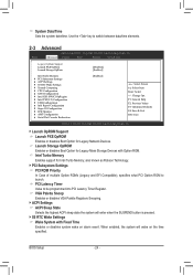
... Report Configuration } Super IO Configuration } H/W Monitor } AMT Configuration } Serial Port Console Redirection [Enabled] : Select Screen : Select Item Enter: Select +/-: Change Opt. BIOS Setup - 24 - Copyright (C) 2010 American Megatrends, Inc. Launch OpROM Support Launch PXE OpROM Enables or disables Boot Option for Intel Turbo Memory, also known...
... Report Configuration } Super IO Configuration } H/W Monitor } AMT Configuration } Serial Port Console Redirection [Enabled] : Select Screen : Select Item Enter: Select +/-: Change Opt. BIOS Setup - 24 - Copyright (C) 2010 American Megatrends, Inc. Launch OpROM Support Launch PXE OpROM Enables or disables Boot Option for Intel Turbo Memory, also known...
Manual
Page 25
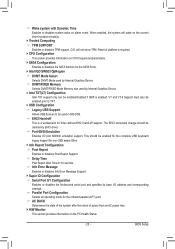
... DVMT/FIXED Mode Memory size used by Internal Graphics Device. This should be claimed by EHCI driver. O.S. Delay Time Post Report Wait TIme:0~10 secinds. BIOS Setup Reset of power from an AC power loss. H/W Monitor This section provides information on CPU frequencies/parameters. SATA Configuration Enables or disables...
... DVMT/FIXED Mode Memory size used by Internal Graphics Device. This should be claimed by EHCI driver. O.S. Delay Time Post Report Wait TIme:0~10 secinds. BIOS Setup Reset of power from an AC power loss. H/W Monitor This section provides information on CPU frequencies/parameters. SATA Configuration Enables or disables...
Manual
Page 26
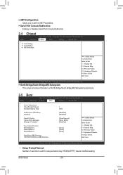
...Boot Option #2 Boot Option #3 Hard Drive BBS Priorities CD/DVD ROM Drive BBS Priorities 1 [Off] [Disabled] [Disabled] [Upon Request] [Force BIOS] [Disabled] [None] [None] [None] : Select Screen : Select Item Enter: Select +/-: Change Opt. Setup Prompt Timeout...Aptio Setup Utility - F1: General Help F2: Previous Values F3: Optimized Defaults F4: Save & Exit ESC: Exit Version 2.10.1208. BIOS Setup - 26 - AMT Configuration Allows you to wait for setup activation key. 65535(0xFFFF) means indefinite waiting. Chipset Boot Security ...
...Boot Option #2 Boot Option #3 Hard Drive BBS Priorities CD/DVD ROM Drive BBS Priorities 1 [Off] [Disabled] [Disabled] [Upon Request] [Force BIOS] [Disabled] [None] [None] [None] : Select Screen : Select Item Enter: Select +/-: Change Opt. Setup Prompt Timeout...Aptio Setup Utility - F1: General Help F2: Previous Values F3: Optimized Defaults F4: Save & Exit ESC: Exit Version 2.10.1208. BIOS Setup - 26 - AMT Configuration Allows you to wait for setup activation key. 65535(0xFFFF) means indefinite waiting. Chipset Boot Security ...
Manual
Page 27
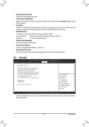
... display made for when entering Setup. If ONLY the User's password is set , then this is executed above 1MB. The password must be disabled using BIOS services. (Default) Always Do not allow disabling GA20. Administrator User Password HDD Security Configuration: : Select Screen : Select Item Enter: Select +/-: Change...
... display made for when entering Setup. If ONLY the User's password is set , then this is executed above 1MB. The password must be disabled using BIOS services. (Default) Always Do not allow disabling GA20. Administrator User Password HDD Security Configuration: : Select Screen : Select Item Enter: Select +/-: Change...
Manual
Page 28
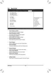
... as User Defaults Restore User Defaults Boot Override SATA: None SATA: None EFIGUI_FLASH : Select Screen : Select Item Enter: Select +/-: Change Opt. BIOS Setup - 28 - Copyright (C) 2010 American Megatrends, Inc. Discard Changes Discard the changes done so far to execute the simple EFI GUI Flash Program. EFIGUI_FLASH Press...
... as User Defaults Restore User Defaults Boot Override SATA: None SATA: None EFIGUI_FLASH : Select Screen : Select Item Enter: Select +/-: Change Opt. BIOS Setup - 28 - Copyright (C) 2010 American Megatrends, Inc. Discard Changes Discard the changes done so far to execute the simple EFI GUI Flash Program. EFIGUI_FLASH Press...
Manual
Page 30
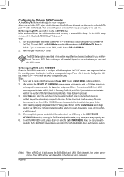
... the stripe block size, press . 4. Press to 128 KB. Under Disks item, select the hard drives to be automatically assigned to enter BIOS Setup during the POST (Power-On Self-Test). Finally press on the number of the hard drives being connected. Appendix - 30 - Then ...capacity and press . When prompted to confirm whether to configure the SATA controller mode correctly in MAIN MENU. Configuring SATA controller mode in BIOS Setup Make sure to create this section may vary depending on the motherboard. After entering the CREATE VOLUME MENU screen, enter a volume name...
... the stripe block size, press . 4. Press to 128 KB. Under Disks item, select the hard drives to be automatically assigned to enter BIOS Setup during the POST (Power-On Self-Test). Finally press on the number of the hard drives being connected. Appendix - 30 - Then ...capacity and press . When prompted to confirm whether to configure the SATA controller mode correctly in MAIN MENU. Configuring SATA controller mode in BIOS Setup Make sure to create this section may vary depending on the motherboard. After entering the CREATE VOLUME MENU screen, enter a volume name...


