Manual
Page 1
GA-P67A-UD7-B3 LGA1155 socket motherboard for Intel® Core™ i7 processors/ Intel® Core™ i5 processors/ Intel® Core™ i3 processors/ Intel® Pentium® processors/ Intel® Celeron® processors User's Manual Rev. 1001 12ME-P67AD7B-1001R
GA-P67A-UD7-B3 LGA1155 socket motherboard for Intel® Core™ i7 processors/ Intel® Core™ i5 processors/ Intel® Core™ i3 processors/ Intel® Pentium® processors/ Intel® Celeron® processors User's Manual Rev. 1001 12ME-P67AD7B-1001R
Manual
Page 2
Motherboard GA-P67A-UD7-B3 Nov. 8, 2010 Motherboard GA-P67A-UD7-B3 Nov. 8, 2010
Motherboard GA-P67A-UD7-B3 Nov. 8, 2010 Motherboard GA-P67A-UD7-B3 Nov. 8, 2010
Manual
Page 4
Table of Contents Box Contents...6 Optional Items...6 GA-P67A-UD7-B3 Motherboard Layout 7 GA-P67A-UD7-B3 Motherboard Block Diagram 8 Chapter 1 Hardware Installation 9 1-1 Installation Precautions 9 1-2 Product Specifications 10 1-3 Installing the CPU and CPU Cooler 13 1-3-1 Installing the CPU 13 1-3-2 Installing the CPU ...
Table of Contents Box Contents...6 Optional Items...6 GA-P67A-UD7-B3 Motherboard Layout 7 GA-P67A-UD7-B3 Motherboard Block Diagram 8 Chapter 1 Hardware Installation 9 1-1 Installation Precautions 9 1-2 Product Specifications 10 1-3 Installing the CPU and CPU Cooler 13 1-3-1 Installing the CPU 13 1-3-2 Installing the CPU ...
Manual
Page 6
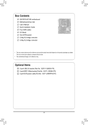
... 2-port USB 2.0 bracket (Part No. 12CR1-1UB030-5*R) 2-port IEEE 1394a bracket (Part No. 12CF1-1IE008-0*R) 2-port SATA power cable (Part No. 12CF1-2SERPW-0*R) - 6 - Box Contents GA-P67A-UD7-B3 motherboard Motherboard driver disk User's Manual Quick Installation Guide Four SATA cables I/O Shield One SATA bracket 2-Way SLI bridge connector 3-Way SLI bridge connector •...
... 2-port USB 2.0 bracket (Part No. 12CR1-1UB030-5*R) 2-port IEEE 1394a bracket (Part No. 12CF1-1IE008-0*R) 2-port SATA power cable (Part No. 12CF1-2SERPW-0*R) - 6 - Box Contents GA-P67A-UD7-B3 motherboard Motherboard driver disk User's Manual Quick Installation Guide Four SATA cables I/O Shield One SATA bracket 2-Way SLI bridge connector 3-Way SLI bridge connector •...
Manual
Page 7
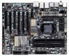
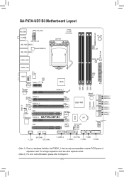
TSB43AB23 PCIEX8_2 GA-P67A-UD7-B3 iTE IT8892 Bridge PCI2 VLI VL810 MD2 MD1 ATX DDR3_1 DDR3_2 DDR3_3 DDR3_4 IT8728 B_BIOS M_BIOS Intel® P67 BAT S4_S5_LED S3_LED S1_LED ... slots. (Note 2) For error code information, please refer to a hardware limitation, the PCIEX1_1 slot can only accommodate a shorter PCI Express x1 expansion card. GA-P67A-UD7-B3 Motherboard Layout KB_USB3 SYS_FAN1 R_SPDIF ATX_12V_2X USB_1394_ESATA_2 Marvell 88SE9128 USB_1394_ESATA_1 LGA1155 CPU_FAN PHASE LED PW_SW RST_SW PWR_FAN USB30_LAN2 CMOS_SW USB30_LAN1 VLI VL810 F_AUDIO AUDIO Renesas...
TSB43AB23 PCIEX8_2 GA-P67A-UD7-B3 iTE IT8892 Bridge PCI2 VLI VL810 MD2 MD1 ATX DDR3_1 DDR3_2 DDR3_3 DDR3_4 IT8728 B_BIOS M_BIOS Intel® P67 BAT S4_S5_LED S3_LED S1_LED ... slots. (Note 2) For error code information, please refer to a hardware limitation, the PCIEX1_1 slot can only accommodate a shorter PCI Express x1 expansion card. GA-P67A-UD7-B3 Motherboard Layout KB_USB3 SYS_FAN1 R_SPDIF ATX_12V_2X USB_1394_ESATA_2 Marvell 88SE9128 USB_1394_ESATA_1 LGA1155 CPU_FAN PHASE LED PW_SW RST_SW PWR_FAN USB30_LAN2 CMOS_SW USB30_LAN1 VLI VL810 F_AUDIO AUDIO Renesas...
Manual
Page 8
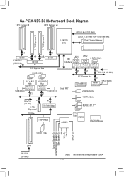
GA-P67A-UD7-B3 Motherboard Block Diagram 2 PCI Express x8 2 PCI Express x8 LGA1155 CPU CPU CLK+/- (100 MHz) DDR3 2133/1866/1600/1333/1066 MHz Dual Channel Memory 1 ...
GA-P67A-UD7-B3 Motherboard Block Diagram 2 PCI Express x8 2 PCI Express x8 LGA1155 CPU CPU CLK+/- (100 MHz) DDR3 2133/1866/1600/1333/1066 MHz Dual Channel Memory 1 ...
Manual
Page 36
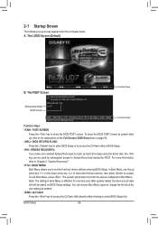
... item on BIOS Setup settings. 2-1 Startup Screen The following screens may appear when the computer boots. To exit Boot Menu, press . Motherboard Model BIOS Version P67A-UD7-B3 F3a . . . . : BIOS Setup : XpressRecovery2 : Boot Menu : Qflash 10/28/2010-P67-7A89UG04C-00 Function Keys Function Keys Function Keys: : POST SCREEN Press the key to...
... item on BIOS Setup settings. 2-1 Startup Screen The following screens may appear when the computer boots. To exit Boot Menu, press . Motherboard Model BIOS Version P67A-UD7-B3 F3a . . . . : BIOS Setup : XpressRecovery2 : Boot Menu : Qflash 10/28/2010-P67-7A89UG04C-00 Function Keys Function Keys Function Keys: : POST SCREEN Press the key to...
Manual
Page 70
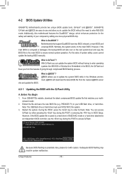
... corrupted or damaged, the backup BIOS will download the latest BIOS file from the hassles of system safety, users cannot update the backup BIOS manually. P67A-UD7-B3 F3a . . . . : BIOS Setup : XpressRecovery2 : Boot Menu : Qflash 10/28/2010-P67-7A89UG04C-00 Because BIOS flashing is @BIOS™? @BIOS ...allows you can access Q-Flash by adding one more physical BIOS chip. P67AUD7.F1) to -use FAT32/16/12 file system. 3. GIGABYTE Q-Flash and @BIOS are easy-to your motherboard model. 2. With Q-Flash you to enter Q-Flash. What is potentially risky, please do it with...
... corrupted or damaged, the backup BIOS will download the latest BIOS file from the hassles of system safety, users cannot update the backup BIOS manually. P67A-UD7-B3 F3a . . . . : BIOS Setup : XpressRecovery2 : Boot Menu : Qflash 10/28/2010-P67-7A89UG04C-00 Because BIOS flashing is @BIOS™? @BIOS ...allows you can access Q-Flash by adding one more physical BIOS chip. P67AUD7.F1) to -use FAT32/16/12 file system. 3. GIGABYTE Q-Flash and @BIOS are easy-to your motherboard model. 2. With Q-Flash you to enter Q-Flash. What is potentially risky, please do it with...


