Manual
Page 7
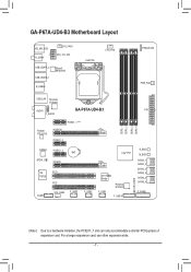
... Layout KB_MS_USB R_SPDIF SYS_FAN1 ATX_12V_2X4 USB_ESATA_2 USB_ESATA_1 Marvell 88SE9128 R_USB30 LGA1155 CPU_FAN PHASE LED PWR_FAN USB_LAN Renesas D720200 AUDIO GA-P67A-UD4-B3 ATX F_AUDIO DDR3_1 DDR3_2 DDR3_3 DDR3_4 Realtek RTL8111E PCIEX1_1 (Note) PCIEX16 PCIEX1_2 CODEC PCIEX1_3 BAT SPDIF_O PCIEX8 iTE PCI1 IT8728 PCI2 COMA SYS_FAN2 F_USB3 F_USB2... D720200 F_USB30 CLR_CMOS B_BIOS M_BIOS SATA3_1 SATA3_0 SATA2_3 SATA2_2 SATA2_5 SATA2_4 F_PANEL (Note) Due to a hardware limitation, the PCIEX1_1 slot can only accommodate a shorter PCI Express x1 expansion card.
... Layout KB_MS_USB R_SPDIF SYS_FAN1 ATX_12V_2X4 USB_ESATA_2 USB_ESATA_1 Marvell 88SE9128 R_USB30 LGA1155 CPU_FAN PHASE LED PWR_FAN USB_LAN Renesas D720200 AUDIO GA-P67A-UD4-B3 ATX F_AUDIO DDR3_1 DDR3_2 DDR3_3 DDR3_4 Realtek RTL8111E PCIEX1_1 (Note) PCIEX16 PCIEX1_2 CODEC PCIEX1_3 BAT SPDIF_O PCIEX8 iTE PCI1 IT8728 PCI2 COMA SYS_FAN2 F_USB3 F_USB2... D720200 F_USB30 CLR_CMOS B_BIOS M_BIOS SATA3_1 SATA3_0 SATA2_3 SATA2_2 SATA2_5 SATA2_4 F_PANEL (Note) Due to a hardware limitation, the PCIEX1_1 slot can only accommodate a shorter PCI Express x1 expansion card.
Manual
Page 8
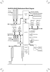
GA-P67A-UD4-B3 Motherboard Block Diagram PCIe CLK (100 MHz) 1 PCI Express x16 or 2 PCI Express x8 LGA1155 CPU CPU CLK+/- (100 MHz) DDR3 2133/1866/1600/1333/1066 MHz Dual Channel Memory x16 x8 Switch DMI Interface PCI Express Bus 2 SATA 6Gb/s LAN RJ45 Marvell Realtek 88SE9128 RTL8111E PCI Express Bus ...x1 x1 Intel® P67 PCIe CLK (100 MHz) x1 x1 x1 x1 3 PCI Express x1 iTE IT8892 Bridge PCI Bus CODEC 2 USB 3.0/2.0 2 USB 3.0/2.0...
GA-P67A-UD4-B3 Motherboard Block Diagram PCIe CLK (100 MHz) 1 PCI Express x16 or 2 PCI Express x8 LGA1155 CPU CPU CLK+/- (100 MHz) DDR3 2133/1866/1600/1333/1066 MHz Dual Channel Memory x16 x8 Switch DMI Interface PCI Express Bus 2 SATA 6Gb/s LAN RJ45 Marvell Realtek 88SE9128 RTL8111E PCI Express Bus ...x1 x1 Intel® P67 PCIe CLK (100 MHz) x1 x1 x1 x1 3 PCI Express x1 iTE IT8892 Bridge PCI Bus CODEC 2 USB 3.0/2.0 2 USB 3.0/2.0...

Manual
Page 10
... 2 x eSATA 6Gb/s connectors on the back panel supporting up to x8 mode. 3 x PCI Express x1 slots (All PCI Express slots conform to PCI Express 2.0 standard.) 2 x PCI slots Multi-Graphics Support for SATA RAID 0, RAID 1, RAID 5, and RAID 10 * When ...GIGABYTE's website for the latest supported memory speeds and memory modules) Realtek ALC892/889 codec High Definition Audio 2/4/5.1/7.1-channel Support for Dolby® Home Theater Support for S/PDIF Out LAN 1 x Realtek RTL8111E chip (10/100/1000 Mbit) Expansion Slots 1 x PCI Express...
... 2 x eSATA 6Gb/s connectors on the back panel supporting up to x8 mode. 3 x PCI Express x1 slots (All PCI Express slots conform to PCI Express 2.0 standard.) 2 x PCI slots Multi-Graphics Support for SATA RAID 0, RAID 1, RAID 5, and RAID 10 * When ...GIGABYTE's website for the latest supported memory speeds and memory modules) Realtek ALC892/889 codec High Definition Audio 2/4/5.1/7.1-channel Support for Dolby® Home Theater Support for S/PDIF Out LAN 1 x Realtek RTL8111E chip (10/100/1000 Mbit) Expansion Slots 1 x PCI Express...

Manual
Page 18
... installing all expansion cards, replace the chassis cover(s). 6. Make sure the card is fully inserted into the slot. 4. PCI Express x1 Slot PCI Express x16 Slot PCI Slot Follow the steps below to make any required BIOS changes for your expansion card. • Always turn off the ...the card straight up from the chassis back panel. 2. Example: Installing and Removing a PCI Express Graphics Card: • Installing a Graphics Card: Gently push down on the top edge of the PCI Express slot to install an expansion card: • Make sure the motherboard supports the expansion card...
... installing all expansion cards, replace the chassis cover(s). 6. Make sure the card is fully inserted into the slot. 4. PCI Express x1 Slot PCI Express x16 Slot PCI Slot Follow the steps below to make any required BIOS changes for your expansion card. • Always turn off the ...the card straight up from the chassis back panel. 2. Example: Installing and Removing a PCI Express Graphics Card: • Installing a Graphics Card: Gently push down on the top edge of the PCI Express slot to install an expansion card: • Make sure the motherboard supports the expansion card...
Manual
Page 19
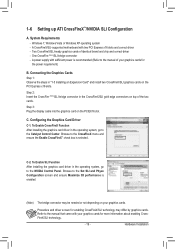
... CrossFireX/SLI technology. - 19 - Connecting the Graphics Cards Step 1: Observe the steps in the CrossFireX/SLI gold edge connectors on the PCI Express x16 slots. Step 2: Insert the CrossFire (Note)/SLI bridge connector in "1-5 Installing an Expansion Card" and install two CrossFireX/SLI graphics ...to the Set SLI and Physx Configuration screen and ensure Maximize 3D performance is selected. Browse to the manual that came with two PCI Express x16 slots and correct driver - Refer to the CrossFireX menu and ensure the Enable CrossFireX™ check box is enabled. (Note...
... CrossFireX/SLI technology. - 19 - Connecting the Graphics Cards Step 1: Observe the steps in the CrossFireX/SLI gold edge connectors on the PCI Express x16 slots. Step 2: Insert the CrossFire (Note)/SLI bridge connector in "1-5 Installing an Expansion Card" and install two CrossFireX/SLI graphics ...to the Set SLI and Physx Configuration screen and ensure Maximize 3D performance is selected. Browse to the manual that came with two PCI Express x16 slots and correct driver - Refer to the CrossFireX menu and ensure the Enable CrossFireX™ check box is enabled. (Note...
Manual
Page 46
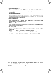
...Allows you to set this item to initialize the hard drive as the first display. (Note) This item is from the installed PCI graphics card or the PCI Express graphics card. Limit CPUID Max. The adjustable range is present only when you to determine whether to 15 seconds. (Default: ... displays normal POST message. (Default: Enabled) Init Display First Specifies the first initiation of the monitor display from 0 to display the GIGABYTE Logo at system startup. set a delay time for the computer, reducing exposure to viruses and malicious buffer overflow attacks when working with ...
...Allows you to set this item to initialize the hard drive as the first display. (Note) This item is from the installed PCI graphics card or the PCI Express graphics card. Limit CPUID Max. The adjustable range is present only when you to determine whether to 15 seconds. (Default: ... displays normal POST message. (Default: Enabled) Init Display First Specifies the first initiation of the monitor display from 0 to display the GIGABYTE Logo at system startup. set a delay time for the computer, reducing exposure to viruses and malicious buffer overflow attacks when working with ...


