Manual
Page 3
... may be reproduced, copied, translated, transmitted, or published in this manual may be made by any form or by GIGABYTE without GIGABYTE's prior written permission. Copyright © 2011 GIGA-BYTE TECHNOLOGY CO., LTD. All rights reserved. No part of the...User's Manual. Example: For product-related information, check on our website at: http://www.gigabyte.com Identifying Your Motherboard Revision The revision number on your motherboard revision before updating motherboard BIOS, drivers, or when looking for technical information. Changes to their respective owners.
... may be reproduced, copied, translated, transmitted, or published in this manual may be made by any form or by GIGABYTE without GIGABYTE's prior written permission. Copyright © 2011 GIGA-BYTE TECHNOLOGY CO., LTD. All rights reserved. No part of the...User's Manual. Example: For product-related information, check on our website at: http://www.gigabyte.com Identifying Your Motherboard Revision The revision number on your motherboard revision before updating motherboard BIOS, drivers, or when looking for technical information. Changes to their respective owners.
Manual
Page 4
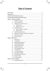
Table of Contents Box Contents...6 Optional Items...6 GA-P67A-UD4-B3 Motherboard Layout 7 GA-P67A-UD4-B3 Motherboard Block Diagram 8 Chapter 1 Hardware Installation 9 1-1 Installation Precautions 9 1-2 Product Specifications 10 1-3 Installing the CPU and CPU Cooler ... SLI Configuration 19 1-7 Back Panel Connectors 20 1-8 Internal Connectors 22 Chapter 2 BIOS Setup 31 2-1 Startup Screen 32 2-2 The Main Menu 33 2-3 MB Intelligent Tweaker(M.I.T 35 2-4 Standard CMOS Features 43 2-5 Advanced BIOS Features 45 2-6 Integrated Peripherals 47 2-7 Power Management Setup 50 2-8 PC Health ...
Table of Contents Box Contents...6 Optional Items...6 GA-P67A-UD4-B3 Motherboard Layout 7 GA-P67A-UD4-B3 Motherboard Block Diagram 8 Chapter 1 Hardware Installation 9 1-1 Installation Precautions 9 1-2 Product Specifications 10 1-3 Installing the CPU and CPU Cooler ... SLI Configuration 19 1-7 Back Panel Connectors 20 1-8 Internal Connectors 22 Chapter 2 BIOS Setup 31 2-1 Startup Screen 32 2-2 The Main Menu 33 2-3 MB Intelligent Tweaker(M.I.T 35 2-4 Standard CMOS Features 43 2-5 Advanced BIOS Features 45 2-6 Integrated Peripherals 47 2-7 Power Management Setup 50 2-8 PC Health ...

Manual
Page 5
... 58 3-4 Contact...59 3-5 System...59 3-6 Download Center 60 3-7 New Utilities...60 Chapter 4 Unique Features 61 4-1 Xpress Recovery2 61 4-2 BIOS Update Utilities 64 4-2-1 Updating the BIOS with the Q-Flash Utility 64 4-2-2 Updating the BIOS with the @BIOS Utility 67 4-3 EasyTune 6...68 4-4 Dynamic Energy Saver™ 2 69 4-5 Q-Share...71 4-6 Smart 6™ ...72 4-7 Auto Green...76 4-8 eXtreme...
... 58 3-4 Contact...59 3-5 System...59 3-6 Download Center 60 3-7 New Utilities...60 Chapter 4 Unique Features 61 4-1 Xpress Recovery2 61 4-2 BIOS Update Utilities 64 4-2-1 Updating the BIOS with the Q-Flash Utility 64 4-2-2 Updating the BIOS with the @BIOS Utility 67 4-3 EasyTune 6...68 4-4 Dynamic Energy Saver™ 2 69 4-5 Q-Share...71 4-6 Smart 6™ ...72 4-7 Auto Green...76 4-8 eXtreme...
Manual
Page 8
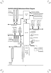
GA-P67A-UD4-B3 Motherboard Block Diagram PCIe CLK (100 MHz) 1 PCI Express x16 or 2 PCI Express x8 LGA1155 CPU CPU CLK+/- (100 MHz) DDR3 2133/1866/1600/1333/...) x1 x1 x1 x1 3 PCI Express x1 iTE IT8892 Bridge PCI Bus CODEC 2 USB 3.0/2.0 2 USB 3.0/2.0 Renesas D720200 Renesas D720200 x1 x1 PCI Express Bus Dual BIOS 4 SATA 3Gb/s 2 SATA 6Gb/s 14 USB 2.0/1.1 LPC Bus iTE IT8728 COM Port PS/2 KB/Mouse Surround Speaker Out Center/Subwoofer Speaker Out Side Speaker Out...
GA-P67A-UD4-B3 Motherboard Block Diagram PCIe CLK (100 MHz) 1 PCI Express x16 or 2 PCI Express x8 LGA1155 CPU CPU CLK+/- (100 MHz) DDR3 2133/1866/1600/1333/...) x1 x1 x1 x1 3 PCI Express x1 iTE IT8892 Bridge PCI Bus CODEC 2 USB 3.0/2.0 2 USB 3.0/2.0 Renesas D720200 Renesas D720200 x1 x1 PCI Express Bus Dual BIOS 4 SATA 3Gb/s 2 SATA 6Gb/s 14 USB 2.0/1.1 LPC Bus iTE IT8728 COM Port PS/2 KB/Mouse Surround Speaker Out Center/Subwoofer Speaker Out Side Speaker Out...

Manual
Page 11
... (Center/Subwoofer Speaker Out/Rear Speaker Out/ Side Speaker Out/Line In/Line Out/Microphone) I/O Controller w iTE IT8728 chip Hardware Monitor w w w w w w BIOS w w w w System voltage detection CPU/System temperature detection CPU/System/Power fan speed detection CPU overheating warning CPU/System/Power fan fail warning CPU/System fan...: - Hardware Installation Up to 4 USB 3.0/2.0 ports (2 on the CPU/system cooler you install. 2 x 32 Mbit flash Use of licensed AWARD BIOS Support for DualBIOS™ PnP 1.0a, DMI 2.0, SM...
... (Center/Subwoofer Speaker Out/Rear Speaker Out/ Side Speaker Out/Line In/Line Out/Microphone) I/O Controller w iTE IT8728 chip Hardware Monitor w w w w w w BIOS w w w w System voltage detection CPU/System temperature detection CPU/System/Power fan speed detection CPU overheating warning CPU/System/Power fan fail warning CPU/System fan...: - Hardware Installation Up to 4 USB 3.0/2.0 ports (2 on the CPU/system cooler you install. 2 x 32 Mbit flash Use of licensed AWARD BIOS Support for DualBIOS™ PnP 1.0a, DMI 2.0, SM...
Manual
Page 12
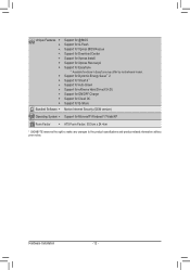
... - 12 - Unique Features w w w w w w w w w w w w w w Bundled Software w Support for @BIOS Support for Q-Flash Support for Xpress BIOS Rescue Support for Download Center Support for Xpress Install Support for Xpress Recovery2 Support for Microsoft® Windows® 7/Vista/XP Form... Factor w ATX Form Factor; 30.5cm x 24.4cm * GIGABYTE reserves the...
... - 12 - Unique Features w w w w w w w w w w w w w w Bundled Software w Support for @BIOS Support for Q-Flash Support for Xpress BIOS Rescue Support for Download Center Support for Xpress Install Support for Xpress Recovery2 Support for Microsoft® Windows® 7/Vista/XP Form... Factor w ATX Form Factor; 30.5cm x 24.4cm * GIGABYTE reserves the...

Manual
Page 16
...that memory of the same capacity, brand, speed, and chips be installed in Dual Channel mode. 1. After the memory is installed, the BIOS will double the original memory bandwidth. DS/SS DS/SS (SS=Single-Sided, DS=Double-Sided, "- -"=No Memory) DDR3_1 DDR3_2 DDR3_3... DDR3_4 Due to prevent hardware damage. • Memory modules have a foolproof design. Dual Channel mode cannot be used . (Go to GIGABYTE's website for optimum performance. Enabling Dual Channel memory mode will automatically detect the specifications and capacity of the same capacity, brand, speed, and ...
...that memory of the same capacity, brand, speed, and chips be installed in Dual Channel mode. 1. After the memory is installed, the BIOS will double the original memory bandwidth. DS/SS DS/SS (SS=Single-Sided, DS=Double-Sided, "- -"=No Memory) DDR3_1 DDR3_2 DDR3_3... DDR3_4 Due to prevent hardware damage. • Memory modules have a foolproof design. Dual Channel mode cannot be used . (Go to GIGABYTE's website for optimum performance. Enabling Dual Channel memory mode will automatically detect the specifications and capacity of the same capacity, brand, speed, and ...

Manual
Page 18
... card to prevent hardware damage. PCI Express x1 Slot PCI Express x16 Slot PCI Slot Follow the steps below to make any required BIOS changes for your operating system. Remove the metal slot cover from the slot. Make sure the card is securely seated in your expansion...(s). 7. Carefully read the manual that supports your computer. Hardware Installation - 18 - Align the card with a screw. 5. If necessary, go to BIOS Setup to correctly install your expansion card. • Always turn off the computer and unplug the power cord from the power outlet before you begin...
... card to prevent hardware damage. PCI Express x1 Slot PCI Express x16 Slot PCI Slot Follow the steps below to make any required BIOS changes for your operating system. Remove the metal slot cover from the slot. Make sure the card is securely seated in your expansion...(s). 7. Carefully read the manual that supports your computer. Hardware Installation - 18 - Align the card with a screw. 5. If necessary, go to BIOS Setup to correctly install your expansion card. • Always turn off the computer and unplug the power cord from the power outlet before you begin...

Manual
Page 24
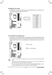
... the battery holder and wait for 5 seconds.) 3. Gently remove the battery from overheating. mended that a system fan be sure to keep the values (such as BIOS configurations, date, and time information) in the correct orientation (the black connector wire is turned off. Definition 1 GND 1 2 +12V / Speed Control SYS_FAN2 3 Sense 4 Reserve SYS_FAN1...
... the battery holder and wait for 5 seconds.) 3. Gently remove the battery from overheating. mended that a system fan be sure to keep the values (such as BIOS configurations, date, and time information) in the correct orientation (the black connector wire is turned off. Definition 1 GND 1 2 +12V / Speed Control SYS_FAN2 3 Sense 4 Reserve SYS_FAN1...

Manual
Page 26
... by issuing a beep code. PW+ PWSPEAK+ SPEAK- 2 20 1 19 HD+ HD- When connecting your system using the power switch (refer to Chapter 2, "BIOS Setup," "Power Management Setup," for information about beep codes. • HD (Hard Drive Activity LED, Blue) Connects to the hard drive activity LED on the... when the hard drive is detected at system startup. Hardware Installation - 26 - The LED S0 On is on when the system is detected, the BIOS may configure the way to turn off (S5). • PW (Power Switch, Red): Connects to the power switch on the chassis front panel....
... by issuing a beep code. PW+ PWSPEAK+ SPEAK- 2 20 1 19 HD+ HD- When connecting your system using the power switch (refer to Chapter 2, "BIOS Setup," "Power Management Setup," for information about beep codes. • HD (Hard Drive Activity LED, Blue) Connects to the hard drive activity LED on the... when the hard drive is detected at system startup. Hardware Installation - 26 - The LED S0 On is on when the system is detected, the BIOS may configure the way to turn off (S5). • PW (Power Switch, Red): Connects to the power switch on the chassis front panel....
Manual
Page 29
... optional COM port cable, please contact the local dealer. Open: Normal Short: Clear CMOS Values • Always turn off your computer, be sure to Chapter 2, "BIOS Setup," for a few seconds. Definition 1 NDCD- 9 1 2 NSIN 10 2 3 NSOUT 4 NDTR- 5 GND 6 NDSR- 7 NRTS- 8 NCTS- 9 NRI- 10 No ... motherboard. • After system restart, go to BIOS Setup to load factory defaults (select Load Optimized Defaults) or manually configure the BIOS settings (refer to remove the jumper cap from the jumper. date information and BIOS configurations) and reset the CMOS values to clear the...
... optional COM port cable, please contact the local dealer. Open: Normal Short: Clear CMOS Values • Always turn off your computer, be sure to Chapter 2, "BIOS Setup," for a few seconds. Definition 1 NDCD- 9 1 2 NSIN 10 2 3 NSOUT 4 NDTR- 5 GND 6 NDSR- 7 NRTS- 8 NCTS- 9 NRI- 10 No ... motherboard. • After system restart, go to BIOS Setup to load factory defaults (select Load Optimized Defaults) or manually configure the BIOS settings (refer to remove the jumper cap from the jumper. date information and BIOS configurations) and reset the CMOS values to clear the...
Manual
Page 31
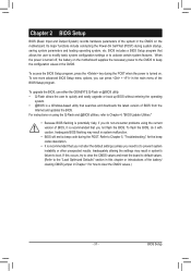
To upgrade the BIOS, use either the GIGABYTE Q-Flash or @BIOS utility. • Q-Flash allows the user to quickly and easily upgrade or back up BIOS without entering the operating system. • @BIOS is turned off, the battery on the motherboard supplies the necessary power to the CMOS to activate certain system ...try to clear the CMOS values and reset the board to default values. (Refer to clear the CMOS values.) - 31 - To see more advanced BIOS Setup menu options, you can press + in Chapter 1 for the beep codes description. • It is recommended that you not alter the default...
To upgrade the BIOS, use either the GIGABYTE Q-Flash or @BIOS utility. • Q-Flash allows the user to quickly and easily upgrade or back up BIOS without entering the operating system. • @BIOS is turned off, the battery on the motherboard supplies the necessary power to the CMOS to activate certain system ...try to clear the CMOS values and reset the board to default values. (Refer to clear the CMOS values.) - 31 - To see more advanced BIOS Setup menu options, you can press + in Chapter 1 for the beep codes description. • It is recommended that you not alter the default...
Manual
Page 32
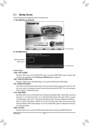
...Screen LOGO Show item on BIOS Setup settings. BIOS Setup - 32 - To show the BIOS POST screen. To exit Boot Menu, press . The POST Screen Award Modular BIOS v6.00PG Copyright (C) 1984-2010, Award Software, Inc. Motherboard Model BIOS Version P67A-UD4-B3 F4f . . . . : BIOS Setup : XpressRecovery2 : ...Boot Menu : Qflash 11/12/2010-P67-7A89UG01C-00 Function Keys Function Keys Function Keys: : POST SCREEN Press the key to show the BIOS POST screen at system startup, refer to...
...Screen LOGO Show item on BIOS Setup settings. BIOS Setup - 32 - To show the BIOS POST screen. To exit Boot Menu, press . The POST Screen Award Modular BIOS v6.00PG Copyright (C) 1984-2010, Award Software, Inc. Motherboard Model BIOS Version P67A-UD4-B3 F4f . . . . : BIOS Setup : XpressRecovery2 : ...Boot Menu : Qflash 11/12/2010-P67-7A89UG01C-00 Function Keys Function Keys Function Keys: : POST SCREEN Press the key to show the BIOS POST screen at system startup, refer to...

Manual
Page 33
... + to access more advanced options. • When the system is not stable as shown below) appears on the screen. BIOS Setup Press to BIOS Load CMOS from BIOS Main Menu Help The on-screen description of a highlighted setup option is displayed on the right (submenus only) Restore the previous... Without Saving ESC: Quit F8: Q-Flash Select Item F10: Save & Exit Setup Change CPU's Clock & Voltage F11: Save CMOS to BIOS F12: Load CMOS from BIOS BIOS Setup Program Function Keys Move the selection bar to select an item Execute command or enter the submenu Main Menu: Exit the...
... + to access more advanced options. • When the system is not stable as shown below) appears on the screen. BIOS Setup Press to BIOS Load CMOS from BIOS Main Menu Help The on-screen description of a highlighted setup option is displayed on the right (submenus only) Restore the previous... Without Saving ESC: Quit F8: Q-Flash Select Item F10: Save & Exit Setup Change CPU's Clock & Voltage F11: Save CMOS to BIOS F12: Load CMOS from BIOS BIOS Setup Program Function Keys Move the selection bar to select an item Execute command or enter the submenu Main Menu: Exit the...
Manual
Page 34
... F12: Load CMOS from a profile created before, without the hassles of errors that stop the system boot, etc. Advanced BIOS Features Use this menu to configure the device boot order, advanced features available on the CPU, and the primary display adapter. Integrated ...or disable password. The Functions of your system becomes unstable and you have loaded the BIOS default settings, you can also carry out this menu to configure all the changes made in BIOS Setup. Set User Password Change, set , or disable password. A supervisor password allows ...
... F12: Load CMOS from a profile created before, without the hassles of errors that stop the system boot, etc. Advanced BIOS Features Use this menu to configure the device boot order, advanced features available on the CPU, and the primary display adapter. Integrated ...or disable password. The Functions of your system becomes unstable and you have loaded the BIOS default settings, you can also carry out this menu to configure all the changes made in BIOS Setup. Set User Password Change, set , or disable password. A supervisor password allows ...

Manual
Page 35
...Miscellaneous Settings [Press Enter] [Press Enter] [Press Enter] [Press Enter] [Press Enter] Item Help Menu Level BIOS Version BCLK CPU Frequency Memory Frequency Total Memory Size F4f 99.80 MHz 3094.12 MHz 1332.71 MHz 1024 MB CPU ...(Inadequately altering the settings may result in system's failure to CPU, chipset, or memory and reduce the useful life of these components. BIOS Setup 2-3 MB Intelligent Tweaker(M.I.T.) CMOS Setup Utility-Copyright (C) 1984-2010 Award Software MB Intelligent Tweaker(M.I.T.) } M.I .T Current Status } ...
...Miscellaneous Settings [Press Enter] [Press Enter] [Press Enter] [Press Enter] [Press Enter] Item Help Menu Level BIOS Version BCLK CPU Frequency Memory Frequency Total Memory Size F4f 99.80 MHz 3094.12 MHz 1332.71 MHz 1024 MB CPU ...(Inadequately altering the settings may result in system's failure to CPU, chipset, or memory and reduce the useful life of these components. BIOS Setup 2-3 MB Intelligent Tweaker(M.I.T.) CMOS Setup Utility-Copyright (C) 1984-2010 Award Software MB Intelligent Tweaker(M.I.T.) } M.I .T Current Status } ...

Manual
Page 36
... present only when you to alter the clock ratio for the installed CPU. For more information about Intel CPUs' unique features, please visit Intel's website. BIOS Setup - 36 - M.I.T. Current Status This screen provides information on the CPU being installed. (Note 1) This item is present only when you install a memory module...
... present only when you to alter the clock ratio for the installed CPU. For more information about Intel CPUs' unique features, please visit Intel's website. BIOS Setup - 36 - M.I.T. Current Status This screen provides information on the CPU being installed. (Note 1) This item is present only when you install a memory module...
Manual
Page 37
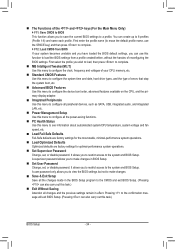
...- The Intel Turbo Boost technology and associated items below will be reduced during system halt state to decrease power consumption. Auto lets the BIOS automatically configure this setting. (Default: Auto) C3/C6 State Support (Note) Allows you to determine whether to set a current limit ...Turbo Ratio (1-Core)/(2-Core)/(3-Core)/(4-Core) (Note) Allows you to set a power limit for different number of active cores. Auto lets the BIOS automatically configure this function. Auto sets the CPU Turbo ratios according to the CPU specifications. (Default: Auto) Turbo Power Limit (Watts) ...
...- The Intel Turbo Boost technology and associated items below will be reduced during system halt state to decrease power consumption. Auto lets the BIOS automatically configure this setting. (Default: Auto) C3/C6 State Support (Note) Allows you to determine whether to set a current limit ...Turbo Ratio (1-Core)/(2-Core)/(3-Core)/(4-Core) (Note) Allows you to set a power limit for different number of active cores. Auto lets the BIOS automatically configure this function. Auto sets the CPU Turbo ratios according to the CPU specifications. (Default: Auto) Turbo Power Limit (Watts) ...
Manual
Page 38
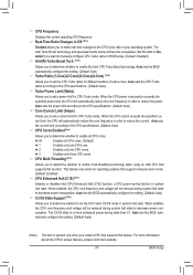
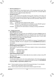
...) CPU EIST Function (Note 1) Enables or disables Enhanced Intel SpeedStep Technology (EIST). Extreme Memory Profile (X.M.P.) (Note 2) Allows the BIOS to read the SPD data on CPU loading, Intel EIST technology can dynamically and effectively lower the CPU voltage and core frequency to ... is automatically adjusted according to 2000 MHz. When enabled, the CPU core frequency and voltage will be configurable. Auto lets the BIOS automatically configure this function. (Default) Profile1 Uses Profile 1 settings. Disabled Disables this set the CPU base clock and DMI/PCIe...
...) CPU EIST Function (Note 1) Enables or disables Enhanced Intel SpeedStep Technology (EIST). Extreme Memory Profile (X.M.P.) (Note 2) Allows the BIOS to read the SPD data on CPU loading, Intel EIST technology can dynamically and effectively lower the CPU voltage and core frequency to ... is automatically adjusted according to 2000 MHz. When enabled, the CPU core frequency and voltage will be configurable. Auto lets the BIOS automatically configure this function. (Default) Profile1 Uses Profile 1 settings. Disabled Disables this set the CPU base clock and DMI/PCIe...

Manual
Page 39
.... Standard Lets the system operate at its basic performance level. Channel Interleaving Enables or disables memory channel interleaving. Auto lets the BIOS automatically configure this setting. (Default: Auto) (Note) This item is set to increase memory performance and stability. Enabled allows ... or Profile2, this item will display the value based on the SPD data on the CPU being used. Auto lets the BIOS automatically configure this feature. - 39 - Enabled allows the system to simultaneously access different ranks of the memory to Disabled, this...
.... Standard Lets the system operate at its basic performance level. Channel Interleaving Enables or disables memory channel interleaving. Auto lets the BIOS automatically configure this setting. (Default: Auto) (Note) This item is set to increase memory performance and stability. Enabled allows ... or Profile2, this item will display the value based on the SPD data on the CPU being used. Auto lets the BIOS automatically configure this feature. - 39 - Enabled allows the system to simultaneously access different ranks of the memory to Disabled, this...


