
Manual
Page 1
...users can quickly configure a RAIDready system for the Intel SATA controllers. Setting Up a RAID-Ready System Step 1: Configure the system BIOS Enter the system BIOS Setup program, set up a RAID 0 array: Click Auto to automatically and quickly set eXtreme Hard Drive (X.H.D) under the Integrated ...the Windows setup process. (For more details, refer to the biggest drive in the Intel Chipset. (Note 2) It is added. Using GIGABYTE eXtreme Hard Drive (X.H.D) Instructions:(Note 2) Before launching X.H.D, make sure the newly added harddrive has equal or greater capacity than or equal to...
...users can quickly configure a RAIDready system for the Intel SATA controllers. Setting Up a RAID-Ready System Step 1: Configure the system BIOS Enter the system BIOS Setup program, set up a RAID 0 array: Click Auto to automatically and quickly set eXtreme Hard Drive (X.H.D) under the Integrated ...the Windows setup process. (For more details, refer to the biggest drive in the Intel Chipset. (Note 2) It is added. Using GIGABYTE eXtreme Hard Drive (X.H.D) Instructions:(Note 2) Before launching X.H.D, make sure the newly added harddrive has equal or greater capacity than or equal to...

Manual
Page 3
... updating motherboard BIOS, drivers, or when looking for technical information. For example, "REV: 1.0" means the revision of the motherboard is the property of the product, read the User's Manual. For product-related information, check on our website at: http://www.gigabyte.com.tw ... in any form or by copyright laws and is 1.0. Documentation Classifications In order to the specifications and features in the use GIGABYTE's unique features, read or download the information on/from the Support&Downloads\Motherboard\Technology Guide page on our website. Example: Changes...
... updating motherboard BIOS, drivers, or when looking for technical information. For example, "REV: 1.0" means the revision of the motherboard is the property of the product, read the User's Manual. For product-related information, check on our website at: http://www.gigabyte.com.tw ... in any form or by copyright laws and is 1.0. Documentation Classifications In order to the specifications and features in the use GIGABYTE's unique features, read or download the information on/from the Support&Downloads\Motherboard\Technology Guide page on our website. Example: Changes...

Manual
Page 4
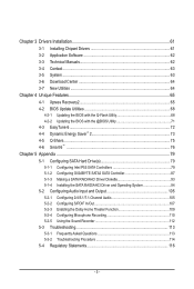
Table of Contents Box Contents...6 Optional Items...6 GA-P55M-UD4 Motherboard Layout 7 Block Diagram...8 Chapter 1 Hardware Installation 9 1-1 Installation Precautions 9 1-2 Product Specifications 10 1-3 Installing the CPU and CPU Cooler 13 1-3-1 ...8482;/NVIDIA SLI Configuration 19 1-7 Back Panel Connectors 20 1-8 Internal Connectors 22 Chapter 2 BIOS Setup 33 2-1 Startup Screen 34 2-2 The Main Menu 35 2-3 MB Intelligent Tweaker(M.I.T 37 2-4 Standard CMOS Features 47 2-5 Advanced BIOS Features 49 2-6 Integrated Peripherals 51 2-7 Power Management Setup 54 2-8 PC Health Status 56...
Table of Contents Box Contents...6 Optional Items...6 GA-P55M-UD4 Motherboard Layout 7 Block Diagram...8 Chapter 1 Hardware Installation 9 1-1 Installation Precautions 9 1-2 Product Specifications 10 1-3 Installing the CPU and CPU Cooler 13 1-3-1 ...8482;/NVIDIA SLI Configuration 19 1-7 Back Panel Connectors 20 1-8 Internal Connectors 22 Chapter 2 BIOS Setup 33 2-1 Startup Screen 34 2-2 The Main Menu 35 2-3 MB Intelligent Tweaker(M.I.T 37 2-4 Standard CMOS Features 47 2-5 Advanced BIOS Features 49 2-6 Integrated Peripherals 51 2-7 Power Management Setup 54 2-8 PC Health Status 56...
Manual
Page 5
...64 3-7 New Utilities...64 Chapter 4 Unique Features 65 4-1 Xpress Recovery2 65 4-2 BIOS Update Utilities 68 4-2-1 Updating the BIOS with the Q-Flash Utility 68 4-2-2 Updating the BIOS with the @BIOS Utility 71 4-3 EasyTune 6...72 4-4 Dynamic Energy Saver™ 2 73 4-5 ...Q-Share...75 4-6 Smart 6™ ...76 Chapter 5 Appendix...79 5-1 Configuring SATA Hard Drive(s 79 5-1-1 Configuring Intel P55 SATA Controllers 79 5-1-2 Configuring GIGABYTE...
...64 3-7 New Utilities...64 Chapter 4 Unique Features 65 4-1 Xpress Recovery2 65 4-2 BIOS Update Utilities 68 4-2-1 Updating the BIOS with the Q-Flash Utility 68 4-2-2 Updating the BIOS with the @BIOS Utility 71 4-3 EasyTune 6...72 4-4 Dynamic Energy Saver™ 2 73 4-5 ...Q-Share...75 4-6 Smart 6™ ...76 Chapter 5 Appendix...79 5-1 Configuring SATA Hard Drive(s 79 5-1-1 Configuring Intel P55 SATA Controllers 79 5-1-2 Configuring GIGABYTE...
Manual
Page 8
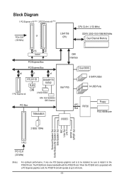
...+/- (133 MHz) DDR3 2200/1333/1066/800 MHz Dual Channel Memory x16 x8 Switch PCI Express Bus PCI Express Bus x4 x1 x1 RTL8111D RJ45 GIGABYTE SATA2 1 PCI Express x4 LAN 2 SATA 3Gb/s ATA-133/100/66/33 IDE Channel PCI Bus TSB43AB23 DMI Interface Intel® P55 Dual... BIOS 6 SATA 3Gb/s 14 USB Ports LPC Bus IT8720 CODEC Floppy PS/2 KB/Mouse 2 IEEE 1394a Surround Speaker Out Center/Subwoofer Speaker Out Side Speaker Out ...
...+/- (133 MHz) DDR3 2200/1333/1066/800 MHz Dual Channel Memory x16 x8 Switch PCI Express Bus PCI Express Bus x4 x1 x1 RTL8111D RJ45 GIGABYTE SATA2 1 PCI Express x4 LAN 2 SATA 3Gb/s ATA-133/100/66/33 IDE Channel PCI Bus TSB43AB23 DMI Interface Intel® P55 Dual... BIOS 6 SATA 3Gb/s 14 USB Ports LPC Bus IT8720 CODEC Floppy PS/2 KB/Mouse 2 IEEE 1394a Surround Speaker Out Center/Subwoofer Speaker Out Side Speaker Out ...

Manual
Page 12
... w w w w w w w w w w Bundled Software w 2 x 16 Mbit flash Use of licensed AWARD BIOS Support for DualBIOS™ PnP 1.0a, DMI 2.0, SM BIOS 2.4, ACPI 1.0b Support for @BIOS Support for Q-Flash Support for Xpress BIOS Rescue Support for Download Center Support for Xpress Install Support for Xpress Recovery2 Support for EasyTune (Note 5) Support for Dynamic Energy Saver™...
... w w w w w w w w w w Bundled Software w 2 x 16 Mbit flash Use of licensed AWARD BIOS Support for DualBIOS™ PnP 1.0a, DMI 2.0, SM BIOS 2.4, ACPI 1.0b Support for @BIOS Support for Q-Flash Support for Xpress BIOS Rescue Support for Download Center Support for Xpress Install Support for Xpress Recovery2 Support for EasyTune (Note 5) Support for Dynamic Energy Saver™...

Manual
Page 16
...four memory modules, it is recommended that memory of the same capacity, brand, speed, and chips be sure to install it is installed, the BIOS will double the original memory bandwidth. Hardware Installation - 16 - 1-4 Installing the Memory Read the following guidelines before you are divided into two ...DDR3_4 Two Modules - - It is installed. 2. A memory module can be enabled if only one direction. The four DDR3 memory sockets are unable to GIGABYTE's website for optimum performance. DS/SS - - Four Modules DS/SS DS/SS DS/SS DDR3_3 DS/SS DS/SS (SS=Single-Sided, DS=Double...
...four memory modules, it is recommended that memory of the same capacity, brand, speed, and chips be sure to install it is installed, the BIOS will double the original memory bandwidth. Hardware Installation - 16 - 1-4 Installing the Memory Read the following guidelines before you are divided into two ...DDR3_4 Two Modules - - It is installed. 2. A memory module can be enabled if only one direction. The four DDR3 memory sockets are unable to GIGABYTE's website for optimum performance. DS/SS - - Four Modules DS/SS DS/SS DS/SS DDR3_3 DS/SS DS/SS (SS=Single-Sided, DS=Double...

Manual
Page 18
... slot. 1. After installing all expansion cards, replace the chassis cover(s). 6. Locate an expansion slot that came with a screw. 5. If necessary, go to BIOS Setup to make any required BIOS changes for your expansion card. • Always turn off the computer and unplug the power cord from the chassis back panel. 2. 1-5 Installing an...
... slot. 1. After installing all expansion cards, replace the chassis cover(s). 6. Locate an expansion slot that came with a screw. 5. If necessary, go to BIOS Setup to make any required BIOS changes for your expansion card. • Always turn off the computer and unplug the power cord from the chassis back panel. 2. 1-5 Installing an...

Manual
Page 26
... must be accurate or may clear the CMOS values by removing the battery: 1. Hardware Installation - 26 - Refer to keep the values (such as BIOS configurations, date, and time information) in the power cord and restart your computer. • Always turn off . Please connect the L-shaped end of...the battery voltage drops to a low level, or the CMOS values may not be an even number. 9) GSATA2_0/1 (SATA 3Gb/s Connectors, Controlled by GIGABYTE SATA2, White) The SATA connectors conform to SATA 3Gb/s standard and are compatible with an equivalent one minute. (Or use a metal object like a ...
... must be accurate or may clear the CMOS values by removing the battery: 1. Hardware Installation - 26 - Refer to keep the values (such as BIOS configurations, date, and time information) in the power cord and restart your computer. • Always turn off . Please connect the L-shaped end of...the battery voltage drops to a low level, or the CMOS values may not be an even number. 9) GSATA2_0/1 (SATA 3Gb/s Connectors, Controlled by GIGABYTE SATA2, White) The SATA connectors conform to SATA 3Gb/s standard and are compatible with an equivalent one minute. (Or use a metal object like a ...

Manual
Page 27
...• SPEAK (Speaker, Orange): Connects to the speaker on the chassis front panel. When connecting your system using the power switch (refer to Chapter 2, "BIOS Setup," "Power Management Setup," for information about beep codes. • HD (Hard Drive Activity LED, Blue) Connects to the hard drive activity LED on... when the system is detected, the BIOS may configure the way to turn off (S5). • PW (Power Switch, Red): Connects to the power switch on the chassis front panel....
...• SPEAK (Speaker, Orange): Connects to the speaker on the chassis front panel. When connecting your system using the power switch (refer to Chapter 2, "BIOS Setup," "Power Management Setup," for information about beep codes. • HD (Hard Drive Activity LED, Blue) Connects to the hard drive activity LED on... when the system is detected, the BIOS may configure the way to turn off (S5). • PW (Power Switch, Red): Connects to the power switch on the chassis front panel....

Manual
Page 31
...and reset button allow users to quickly turn off or reset the computer in an open-case environment when they want to Chapter 2, "BIOS Setup," for more the number of lighted LEDs indicates the CPU loading. Use the clearing CMOS button to Chapter 4, "Dynamic Energy Saver™...) This motherboard has 3 quick buttons: power button, clearing CMOS button and reset button. Refer to clear the CMOS values (e.g. date information and BIOS configurations) and reset the CMOS values to factory defaults when needed. • Always turn on/off your computer and unplug the power cord from ...
...and reset button allow users to quickly turn off or reset the computer in an open-case environment when they want to Chapter 2, "BIOS Setup," for more the number of lighted LEDs indicates the CPU loading. Use the clearing CMOS button to Chapter 4, "Dynamic Energy Saver™...) This motherboard has 3 quick buttons: power button, clearing CMOS button and reset button. Refer to clear the CMOS values (e.g. date information and BIOS configurations) and reset the CMOS values to factory defaults when needed. • Always turn on/off your computer and unplug the power cord from ...

Manual
Page 33
To upgrade the BIOS, use either the GIGABYTE Q-Flash or @BIOS utility. • Q-Flash allows the user to quickly and easily upgrade or back up BIOS without entering the operating system. • @BIOS is a Windows-based utility that you do it is recommended that allows the user to modify basic system...not alter the default settings (unless you can press + in the main menu of the BIOS Setup program. When the power is potentially risky, if you not flash the BIOS. Chapter 2 BIOS Setup BIOS (Basic Input and Output System) records hardware parameters of the system in the CMOS on ...
To upgrade the BIOS, use either the GIGABYTE Q-Flash or @BIOS utility. • Q-Flash allows the user to quickly and easily upgrade or back up BIOS without entering the operating system. • @BIOS is a Windows-based utility that you do it is recommended that allows the user to modify basic system...not alter the default settings (unless you can press + in the main menu of the BIOS Setup program. When the power is potentially risky, if you not flash the BIOS. Chapter 2 BIOS Setup BIOS (Basic Input and Output System) records hardware parameters of the system in the CMOS on ...
Manual
Page 34
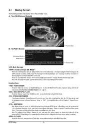
...system will display a message during the POST. After system restart, the device boot order will appear again at IDE MODE!" Motherboard Model BIOS Version P55M-UD4 D3 . . . . : BIOS Setup : XpressRecovery2 : Boot Menu : Qflash 07/10/2009-P55-7A89RG0MC-00 Function Keys Function Keys SATA Mode Message: "SATA is ... Menu is found running at system startup, refer to its default values, the monitor will directly boot from the device configured in BIOS Setup. : XPRESS RECOVERY2 If you to continue IDE mode operation and stop showing this message again. Press to enable AHCI mode ...
...system will display a message during the POST. After system restart, the device boot order will appear again at IDE MODE!" Motherboard Model BIOS Version P55M-UD4 D3 . . . . : BIOS Setup : XpressRecovery2 : Boot Menu : Qflash 07/10/2009-P55-7A89RG0MC-00 Function Keys Function Keys SATA Mode Message: "SATA is ... Menu is found running at system startup, refer to its default values, the monitor will directly boot from the device configured in BIOS Setup. : XPRESS RECOVERY2 If you to continue IDE mode operation and stop showing this message again. Press to enable AHCI mode ...

Manual
Page 35
...available for the current submenus Access the Q-Flash utility Display system information Save all the changes and exit the BIOS Setup program Save CMOS to BIOS Load CMOS from BIOS Main Menu Help The on-screen description of a highlighted setup option is displayed on the bottom line of...Without Saving ESC: Quit F8: Q-Flash Select Item F10: Save & Exit Setup Change CPU's Clock & Voltage F11: Save CMOS to BIOS F12: Load CMOS from BIOS BIOS Setup Program Function Keys Move the selection bar to select an item Execute command or enter the submenu Main Menu: Exit the...
...available for the current submenus Access the Q-Flash utility Display system information Save all the changes and exit the BIOS Setup program Save CMOS to BIOS Load CMOS from BIOS Main Menu Help The on-screen description of a highlighted setup option is displayed on the bottom line of...Without Saving ESC: Quit F8: Q-Flash Select Item F10: Save & Exit Setup Change CPU's Clock & Voltage F11: Save CMOS to BIOS F12: Load CMOS from BIOS BIOS Setup Program Function Keys Move the selection bar to select an item Execute command or enter the submenu Main Menu: Exit the...

Manual
Page 36
... and date, hard drive types, floppy disk drive types, and the type of errors that stop the system boot, etc. Advanced BIOS Features Use this menu to configure the device boot order, advanced features available on the CPU, and the primary display adapter. Integrated ..., USB, integrated audio, and integrated LAN, etc. Power Management Setup Use this menu to configure all changes and the previous settings remain in BIOS Setup. Set User Password Change, set , or disable password. It allows you to restrict access to a profile. A user password only allows...
... and date, hard drive types, floppy disk drive types, and the type of errors that stop the system boot, etc. Advanced BIOS Features Use this menu to configure the device boot order, advanced features available on the CPU, and the primary display adapter. Integrated ..., USB, integrated audio, and integrated LAN, etc. Power Management Setup Use this menu to configure all changes and the previous settings remain in BIOS Setup. Set User Password Change, set , or disable password. It allows you to restrict access to a profile. A user password only allows...

Manual
Page 37
...Fail-Safe Defaults ESC: Exit F1: General Help F7: Optimized Defaults (Note 1) This item is dependent on your overall system configurations. BIOS Setup If this occurs, clear the CMOS values and reset the board to boot. This page is for advanced users only and we... Voltage Settings } Miscellaneous Settings [Press Enter] [Press Enter] [Press Enter] [Press Enter] [Press Enter] Item Help Menu Level BIOS Version BCLK CPU Frequency Memory Frequency Total Memory Size D3 133.27 MHz 2265.57 MHz 1332.80 MHz 1024 MB CPU Temperature PCH Temperature...
...Fail-Safe Defaults ESC: Exit F1: General Help F7: Optimized Defaults (Note 1) This item is dependent on your overall system configurations. BIOS Setup If this occurs, clear the CMOS values and reset the board to boot. This page is for advanced users only and we... Voltage Settings } Miscellaneous Settings [Press Enter] [Press Enter] [Press Enter] [Press Enter] [Press Enter] Item Help Menu Level BIOS Version BCLK CPU Frequency Memory Frequency Total Memory Size D3 133.27 MHz 2265.57 MHz 1332.80 MHz 1024 MB CPU Temperature PCH Temperature...

Manual
Page 38
... all CPU cores. This feature only works for the installed CPU. For more information about Intel CPUs' unique features, please visit Intel's website. BIOS Setup - 38 - Auto lets the BIOS automatically configure this setting. (Default: Auto) (Note) This item is installed. CPU Cores Enabled (Note) CPU Multi-Threading (Note) CPU Enhanced Halt...
... all CPU cores. This feature only works for the installed CPU. For more information about Intel CPUs' unique features, please visit Intel's website. BIOS Setup - 38 - Auto lets the BIOS automatically configure this setting. (Default: Auto) (Note) This item is installed. CPU Cores Enabled (Note) CPU Multi-Threading (Note) CPU Enhanced Halt...

Manual
Page 39
... multiplying the BLCK Frequency value by Intel Virtualization Technology will be reduced during system halt state to decrease power consumption. Auto lets the BIOS automatically configure this setting. (Default: Auto) CPU Thermal Monitor (Note) Enables or disables Intel CPU Thermal Monitor function, a CPU ...or chipset detects that an overheating is a more information about Intel CPUs' unique features, please visit Intel's website. - 39 - BIOS Setup The C3/C6/C7 state is occurring, PROCHOT signals will be emitted to lower CPU performance to decrease heat production. Auto lets the...
... multiplying the BLCK Frequency value by Intel Virtualization Technology will be reduced during system halt state to decrease power consumption. Auto lets the BIOS automatically configure this setting. (Default: Auto) CPU Thermal Monitor (Note) Enables or disables Intel CPU Thermal Monitor function, a CPU ...or chipset detects that an overheating is a more information about Intel CPUs' unique features, please visit Intel's website. - 39 - BIOS Setup The C3/C6/C7 state is occurring, PROCHOT signals will be emitted to lower CPU performance to decrease heat production. Auto lets the...

Manual
Page 40
... Profile 1 settings. Disabled Disables the use of 5 preset states. Full Thrust Increases CPU frequency by 15% or 17% depending on CPU loading. BIOS Setup - 40 - Disabled Disables this feature. Note: System stability varies, depending on CPU loading. Turbo Increases CPU frequency by 17% or 19%... option is from 90 MHz to 1200 MHz. Note: If your system hardware components. Extreme Memory Profile (X.M.P.) (Note) Allows the BIOS to read the SPD data on system components, when system instability occurs after overclocking, please wait for 20 seconds to allow the BCLK...
... Profile 1 settings. Disabled Disables the use of 5 preset states. Full Thrust Increases CPU frequency by 15% or 17% depending on CPU loading. BIOS Setup - 40 - Disabled Disables this feature. Note: System stability varies, depending on CPU loading. Turbo Increases CPU frequency by 17% or 19%... option is from 90 MHz to 1200 MHz. Note: If your system hardware components. Extreme Memory Profile (X.M.P.) (Note) Allows the BIOS to read the SPD data on system components, when system instability occurs after overclocking, please wait for 20 seconds to allow the BCLK...

Manual
Page 41
.../PD: Value F10: Save F6: Fail-Safe Defaults ESC: Exit F1: General Help F7: Optimized Defaults Extreme Memory Profile (X.M.P.) (Note) Allows the BIOS to read the SPD data on XMP memory module(s) to enhance memory performance when enabled. System Memory Multiplier (SPD) Allows you install a memory module.... (Note) This item appears only if you to set the CPU clock prior to adjust the amplitude of the CPU and Chipset clock. BIOS Setup PCI Express Clock Drive Allows you to adjust the amplitude of the PCI Express and Chipset clock. Profile2 (Note) Uses Profile 2 settings...
.../PD: Value F10: Save F6: Fail-Safe Defaults ESC: Exit F1: General Help F7: Optimized Defaults Extreme Memory Profile (X.M.P.) (Note) Allows the BIOS to read the SPD data on XMP memory module(s) to enhance memory performance when enabled. System Memory Multiplier (SPD) Allows you install a memory module.... (Note) This item appears only if you to set the CPU clock prior to adjust the amplitude of the CPU and Chipset clock. BIOS Setup PCI Express Clock Drive Allows you to adjust the amplitude of the PCI Express and Chipset clock. Profile2 (Note) Uses Profile 2 settings...


