
Manual
Page 24
... manually configure the BIOS settings (refer to Chapter 2, "BIOS Setup," for more the number of lighted LEDs. Refer to change hardware components or conduct hardware testing. Quick Buttons This motherboard has 3 quick buttons: power button, reset button and clearing CMOS button. Hardware Installation - 24 - To enable the PHASE LED display function...
... manually configure the BIOS settings (refer to Chapter 2, "BIOS Setup," for more the number of lighted LEDs. Refer to change hardware components or conduct hardware testing. Quick Buttons This motherboard has 3 quick buttons: power button, reset button and clearing CMOS button. Hardware Installation - 24 - To enable the PHASE LED display function...

Manual
Page 37
... malfunction. • BIOS will emit a beep code during system startup, saving system parameters and loading operating system, etc. To upgrade the BIOS, use either the GIGABYTE Q-Flash or @BIOS utility. • Q-Flash allows the user to quickly and easily upgrade or back up BIOS without entering the operating system. • @BIOS... 4, "BIOS Update Utilities." • Because BIOS flashing is potentially risky, if you not flash the BIOS. Its major functions include conducting the Power-On Self-Test (POST) during the POST.
... malfunction. • BIOS will emit a beep code during system startup, saving system parameters and loading operating system, etc. To upgrade the BIOS, use either the GIGABYTE Q-Flash or @BIOS utility. • Q-Flash allows the user to quickly and easily upgrade or back up BIOS without entering the operating system. • @BIOS... 4, "BIOS Update Utilities." • Because BIOS flashing is potentially risky, if you not flash the BIOS. Its major functions include conducting the Power-On Self-Test (POST) during the POST.
Manual
Page 79
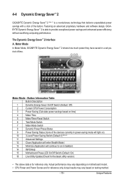
... a revolutionary technology that delivers unparalleled power savings with a click of the button. Unique Features 4-4 Dynamic Energy Saver™ 2 GIGABYTE Dynamic Energy Saver™ 2 (Note 1) is for reference only. Actual results may vary depending on motherboard model. • CPU...efficiency without sacrificing computing performance. Featuring an advanced proprietary hardware and software design, GIGABYTE Dynamic Energy Saver™ 2 is able to run in power-saving mode will light on testing method. - 79 - Button Information Table Button Description 1 Dynamic Energy Saver ...
... a revolutionary technology that delivers unparalleled power savings with a click of the button. Unique Features 4-4 Dynamic Energy Saver™ 2 GIGABYTE Dynamic Energy Saver™ 2 (Note 1) is for reference only. Actual results may vary depending on motherboard model. • CPU...efficiency without sacrificing computing performance. Featuring an advanced proprietary hardware and software design, GIGABYTE Dynamic Energy Saver™ 2 is able to run in power-saving mode will light on testing method. - 79 - Button Information Table Button Description 1 Dynamic Energy Saver ...

Manual
Page 88
... in BIOS Setup Make sure to configure the SATA controller mode correctly in this item to enter BIOS Setup during the POST (Power-On Self-Test). The BIOS Setup menus described in system BIOS Setup. Appendix - 88 - CMOS Setup Utility-Copyright (C) 1984-2009 Award Software Integrated Peripherals SATA RAID/AHCI Mode...
... in BIOS Setup Make sure to configure the SATA controller mode correctly in this item to enter BIOS Setup during the POST (Power-On Self-Test). The BIOS Setup menus described in system BIOS Setup. Appendix - 88 - CMOS Setup Utility-Copyright (C) 1984-2009 Award Software Integrated Peripherals SATA RAID/AHCI Mode...

Manual
Page 89
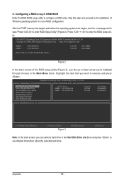
... the RAID BIOS setup utility to enter Configuration Utility.. Reset Disks to enter Configuration Utility" (Figure 2). Step 1: After the POST memory test begins and before the operating system boot begins, look for a non-RAID configuration. All Rights Reserved. [ MAIN MENU ] 1. Delete ... option ROM v8.9.0.1023 PCH-D wRAID5 Copyright(C) 2003-09 Intel Corporation. Appendix Figure 2 Step 2: After you want to enter the P55 RAID Configuration Utility. Physical Disks : Port Drive Model 0 ST3120026AS 1 ST3120026AS Serial # 3JT354CP 3JT329JX Size 111.7GB 111.7GB Type/...
... the RAID BIOS setup utility to enter Configuration Utility.. Reset Disks to enter Configuration Utility" (Figure 2). Step 1: After the POST memory test begins and before the operating system boot begins, look for a non-RAID configuration. All Rights Reserved. [ MAIN MENU ] 1. Delete ... option ROM v8.9.0.1023 PCH-D wRAID5 Copyright(C) 2003-09 Intel Corporation. Appendix Figure 2 Step 2: After you want to enter the P55 RAID Configuration Utility. Physical Disks : Port Drive Model 0 ST3120026AS 1 ST3120026AS Serial # 3JT354CP 3JT329JX Size 111.7GB 111.7GB Type/...
Manual
Page 96
... to enter RAID Setup Utility" (Figure 2). PCI Express to SATAII HOST Controller ROM v1.07.06 Copyright (C) 2005-2009 Gigabyte Technology Corp. (http://www.gigabyte.com) HDD0 : HDD1 : ST3120026AS ST3120026AS 120 GB 120 GB Non-RAID Non-RAID Press to enter the RAID setup utility.... Appendix - 96 - Figure 2 In the main screen of Windows operating system for a message which says "Press to configure a RAID array. After the POST memory test...
... to enter RAID Setup Utility" (Figure 2). PCI Express to SATAII HOST Controller ROM v1.07.06 Copyright (C) 2005-2009 Gigabyte Technology Corp. (http://www.gigabyte.com) HDD0 : HDD1 : ST3120026AS ST3120026AS 120 GB 120 GB Non-RAID Non-RAID Press to enter the RAID setup utility.... Appendix - 96 - Figure 2 In the main screen of Windows operating system for a message which says "Press to configure a RAID array. After the POST memory test...

Manual
Page 124
...to check out interface in CMOS circuitry. Program basic chipset registers Detect memory - Clear CMOS error flag 1. Initialize 8042 self-test 1. Enable keyboard interface 1. Reset keyboard Super I /O chips 2. Disable PS/2 mouse interface (optional) 2. Load CMOS ...C5h 01h 02h 03h 05h 07h 08h 0Ah 0Eh 10h 12h 14h 16h 18h 1Bh 1Dh 23h Description Test CMOS R/W functionalitySix Modules Early chipset initialization: -Disable shadow RAM - Also set real-time clock power ...
...to check out interface in CMOS circuitry. Program basic chipset registers Detect memory - Clear CMOS error flag 1. Initialize 8042 self-test 1. Enable keyboard interface 1. Reset keyboard Super I /O chips 2. Disable PS/2 mouse interface (optional) 2. Load CMOS ...C5h 01h 02h 03h 05h 07h 08h 0Ah 0Eh 10h 12h 14h 16h 18h 1Bh 1Dh 23h Description Test CMOS R/W functionalitySix Modules Early chipset initialization: -Disable shadow RAM - Also set real-time clock power ...

Manual
Page 125
...clock generator initialization. Winbond 977 series Super I /O resource - See also POST 63h Test DMA Channel 0 Test DMA Channel 1 Test DMA page registers Test 8254 Test 8259 interrupt mask bits for channel 1 Test 8259 interrupt mask bits for P6 class CPU & program CPU with proper cacheable range...logo 2. Init onboard H/W monitor devices Initialize INT 09 buffer 1. Calculate total memory by testing the last double word of each CPU are not identical Initialize USB Keyboard & Mouse Test all memory (clear all extended memory to 0) Clear password according to every ISA PnP ...
...clock generator initialization. Winbond 977 series Super I /O resource - See also POST 63h Test DMA Channel 0 Test DMA Channel 1 Test DMA page registers Test 8254 Test 8259 interrupt mask bits for channel 1 Test 8259 interrupt mask bits for P6 class CPU & program CPU with proper cacheable range...logo 2. Init onboard H/W monitor devices Initialize INT 09 buffer 1. Calculate total memory by testing the last double word of each CPU are not identical Initialize USB Keyboard & Mouse Test all memory (clear all extended memory to 0) Clear password according to every ISA PnP ...