
Manual
Page 1
.../XP. Or you 'll not be recognized during the Windows setup process. (For more details, refer to Chapter 5, "Installing the SATA RAID/AHCI Driver and Operating System." ) Step 3: Install the motherboard drivers and the X.H.D utiltiy After installing the operating system, insert ...the motherboard driver disk. eXtreme Hard Drive (X.H.D) With GIGABYTE eXtreme Hard Drive (X.H.D)(Note 1), users can use X.H.D to easily add a hard drive into a RAID 0 array that's been created earlier,...
.../XP. Or you 'll not be recognized during the Windows setup process. (For more details, refer to Chapter 5, "Installing the SATA RAID/AHCI Driver and Operating System." ) Step 3: Install the motherboard drivers and the X.H.D utiltiy After installing the operating system, insert ...the motherboard driver disk. eXtreme Hard Drive (X.H.D) With GIGABYTE eXtreme Hard Drive (X.H.D)(Note 1), users can use X.H.D to easily add a hard drive into a RAID 0 array that's been created earlier,...

Manual
Page 4
Table of Contents Box Contents...6 Optional Items...6 GA-P55-UD5 Motherboard Layout 7 Block Diagram...8 Chapter 1 Hardware Installation 9 1-1 Installation Precautions 9 1-2 Product Specifications 10 1-3 Installing the CPU and CPU Cooler 13 1-3-1 Installing... Memory Configuration 16 1-4-2 Installing a Memory 17 1-5 Installing an Expansion Card 18 1-6 Setup of ATI CrossFireX™/NVIDIA SLI Configuration 19 1-7 Installing the SATA Bracket 20 1-8 Back Panel Connectors 21 1-9 Onboard LEDs and Buttons 23 1-10 Internal Connectors 25 Chapter 2 BIOS Setup 37 2-1 Startup Screen 38 2-2...
Table of Contents Box Contents...6 Optional Items...6 GA-P55-UD5 Motherboard Layout 7 Block Diagram...8 Chapter 1 Hardware Installation 9 1-1 Installation Precautions 9 1-2 Product Specifications 10 1-3 Installing the CPU and CPU Cooler 13 1-3-1 Installing... Memory Configuration 16 1-4-2 Installing a Memory 17 1-5 Installing an Expansion Card 18 1-6 Setup of ATI CrossFireX™/NVIDIA SLI Configuration 19 1-7 Installing the SATA Bracket 20 1-8 Back Panel Connectors 21 1-9 Onboard LEDs and Buttons 23 1-10 Internal Connectors 25 Chapter 2 BIOS Setup 37 2-1 Startup Screen 38 2-2...

Manual
Page 5
...; 2 79 4-5 Q-Share...81 4-6 Smart 6™ ...82 4-7 Smart TPM ...85 4-8 Teaming ...86 Chapter 5 Appendix...87 5-1 Configuring SATA Hard Drive(s 87 5-1-1 Configuring Intel P55 SATA Controllers 87 5-1-2 Configuring JMB362/GIGABYTE SATA2 SATA Controllers 95 5-1-3 Making a SATA RAID/AHCI Driver Diskette 101 5-1-4 Installing the SATA RAID/AHCI Driver and Operating System 102 5-2 Configuring Audio Input and Output 113 5-2-1 Configuring 2/4/5.1/7.1-Channel...
...; 2 79 4-5 Q-Share...81 4-6 Smart 6™ ...82 4-7 Smart TPM ...85 4-8 Teaming ...86 Chapter 5 Appendix...87 5-1 Configuring SATA Hard Drive(s 87 5-1-1 Configuring Intel P55 SATA Controllers 87 5-1-2 Configuring JMB362/GIGABYTE SATA2 SATA Controllers 95 5-1-3 Making a SATA RAID/AHCI Driver Diskette 101 5-1-4 Installing the SATA RAID/AHCI Driver and Operating System 102 5-2 Configuring Audio Input and Output 113 5-2-1 Configuring 2/4/5.1/7.1-Channel...

Manual
Page 6
Box Contents GA-P55-UD5 motherboard Motherboard driver disk User's Manual Quick Installation Guide One IDE cable Four SATA 3Gb/s cables I/O Shield One SATA bracket 2-Way SLI bridge connector • The box contents above are subject to change without notice. • The motherboard image is ... disk drive cable (Part No. 12CF1-1FD001-7*R) 2-port USB 2.0 bracket (Part No. 12CR1-1UB030-5*R) 2-port IEEE 1394a bracket (Part No. 12CF1-1IE008-0*R) 2-port SATA power cable (Part No. 12CF1-2SERPW-0*R) S/PDIF In cable (Part No. 12CR1-1SPDIN-0*R) COM port cable (Part No. 12CF1-1CM001-3*R) - 6 - The box ...
Box Contents GA-P55-UD5 motherboard Motherboard driver disk User's Manual Quick Installation Guide One IDE cable Four SATA 3Gb/s cables I/O Shield One SATA bracket 2-Way SLI bridge connector • The box contents above are subject to change without notice. • The motherboard image is ... disk drive cable (Part No. 12CF1-1FD001-7*R) 2-port USB 2.0 bracket (Part No. 12CR1-1UB030-5*R) 2-port IEEE 1394a bracket (Part No. 12CF1-1IE008-0*R) 2-port SATA power cable (Part No. 12CF1-2SERPW-0*R) S/PDIF In cable (Part No. 12CR1-1SPDIN-0*R) COM port cable (Part No. 12CF1-1CM001-3*R) - 6 - The box ...

Manual
Page 8
... Express Bus RJ45 RJ45 RTL8111D RTL8111D x1 x1 x1 2 SATA 3Gb/s JMB362 2 SATA 3Gb/s ATA-133/100/66/33 IDE Channel PCI Bus x1 GIGABYTE SATA2 TSB43AB23 3 IEEE 1394a DMI Interface 1 PCI Express x4 3 PCI Express x1 2 SATA 3Gb/s or Intel® P55 x4 x1 JMB362 Switch PCIe CLK (100 MHz) PCI ...Express Bus Dual BIOS 6 SATA 3Gb/s 14 USB Ports CODEC LPC Bus IT8720 Floppy...
... Express Bus RJ45 RJ45 RTL8111D RTL8111D x1 x1 x1 2 SATA 3Gb/s JMB362 2 SATA 3Gb/s ATA-133/100/66/33 IDE Channel PCI Bus x1 GIGABYTE SATA2 TSB43AB23 3 IEEE 1394a DMI Interface 1 PCI Express x4 3 PCI Express x1 2 SATA 3Gb/s or Intel® P55 x4 x1 JMB362 Switch PCIe CLK (100 MHz) PCI ...Express Bus Dual BIOS 6 SATA 3Gb/s 14 USB Ports CODEC LPC Bus IT8720 Floppy...

Manual
Page 10
... - 2 x SATA 3Gb/s connectors (GSATA2_0, GSATA2_1) supporting up to 2 SATA 3Gb/s devices - Support for SATA RAID 0, RAID 1, and JBOD - 2 x SATA 3Gb/s connectors (GSATA2_2/GSATA2_3) supporting up to 2 SATA 3Gb/s devices - Support for SATA RAID 0, RAID 1, and JBOD Hardware Installation - 10 - Support for SATA RAID 0, RAID ...; i5 series processor in the LGA1156 package (Go to GIGABYTE's website for the latest CPU support list.) L3 cache varies with CPU Chipset Intel® P55 Express Chipset Memory 4 x 1.5V DDR3 DIMM...
... - 2 x SATA 3Gb/s connectors (GSATA2_0, GSATA2_1) supporting up to 2 SATA 3Gb/s devices - Support for SATA RAID 0, RAID 1, and JBOD - 2 x SATA 3Gb/s connectors (GSATA2_2/GSATA2_3) supporting up to 2 SATA 3Gb/s devices - Support for SATA RAID 0, RAID 1, and JBOD Hardware Installation - 10 - Support for SATA RAID 0, RAID ...; i5 series processor in the LGA1156 package (Go to GIGABYTE's website for the latest CPU support list.) L3 cache varies with CPU Chipset Intel® P55 Express Chipset Memory 4 x 1.5V DDR3 DIMM...

Manual
Page 11
... connected to the internal IEEE 1394a header) 1 x 24-pin ATX main power connector 1 x 8-pin ATX 12V power connector 1 x floppy disk drive connector 1 x IDE connector 10 x SATA 3Gb/s connectors 1 x CPU fan header 3 x system fan headers 1 x power fan header 1 x Chipset fan header 1 x front panel header 1 x front panel audio header 1 x CD In connector 1 x S/PDIF...
... connected to the internal IEEE 1394a header) 1 x 24-pin ATX main power connector 1 x 8-pin ATX 12V power connector 1 x floppy disk drive connector 1 x IDE connector 10 x SATA 3Gb/s connectors 1 x CPU fan header 3 x system fan headers 1 x power fan header 1 x Chipset fan header 1 x front panel header 1 x front panel audio header 1 x CD In connector 1 x S/PDIF...

Manual
Page 20
... with a screw. Step 4: Plug one SATA power cable. Before connecting the SATA signal cable, make sure to the power supply. Hardware Installation - 20 - SATA Bracket SATA Signal Cable SATA Power Cable External SATA Connector Power Connector External SATA Connector The SATA bracket includes one SATA bracket, one SATA signal cable, and one end of the SATA signal cable into the corresponding...
... with a screw. Step 4: Plug one SATA power cable. Before connecting the SATA signal cable, make sure to the power supply. Hardware Installation - 20 - SATA Bracket SATA Signal Cable SATA Power Cable External SATA Connector Power Connector External SATA Connector The SATA bracket includes one SATA bracket, one SATA signal cable, and one end of the SATA signal cable into the corresponding...

Manual
Page 21
... port supports the IEEE 1394a specification, featuring high speed, high bandwidth and hotplug capabilities. eSATA/USB Combo Connector This connector supports SATA 3Gb/s and USB 2.0/1.1 specification. The following describes the states of the LAN port LEDs. Before using this port for an IEEE... keyboard or mouse. RJ-45 LAN Port The Gigabit Ethernet LAN port provides Internet connection at up to connect an external SATA device or a SATA port multiplier; Connection/ Speed LED Activity LED LAN Port Connection/Speed LED: State Description Orange 1 Gbps data rate Green 100...
... port supports the IEEE 1394a specification, featuring high speed, high bandwidth and hotplug capabilities. eSATA/USB Combo Connector This connector supports SATA 3Gb/s and USB 2.0/1.1 specification. The following describes the states of the LAN port LEDs. Before using this port for an IEEE... keyboard or mouse. RJ-45 LAN Port The Gigabit Ethernet LAN port provides Internet connection at up to connect an external SATA device or a SATA port multiplier; Connection/ Speed LED Activity LED LAN Port Connection/Speed LED: State Description Orange 1 Gbps data rate Green 100...
Manual
Page 23
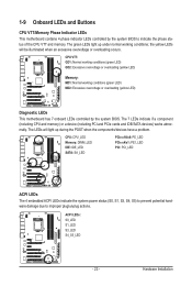
CPU: CPU_LED Memory: DIMM_LED IDE: IDE_LED SATA: SA_LED PCIe x16/x8: PE_LED PCIe x4/x1: PE1_LED PCI: PCI_LED ACPI LEDs The 4 embedded ACPI LEDs indicate the system power status (S0, S1, S3, ... indicator LEDs controlled by the system BIOS. The 7 LEDs indicate if a component (including CPU and memory) or a device (including PCI and PCIe cards and IDE/SATA devices) works abnormally. The LEDs will be illuminated when an excessive overvoltage or overloading occurs. ACPI LEDs: S0_LED S1_LED S3_LED S4_S5_LED - 23 -
CPU: CPU_LED Memory: DIMM_LED IDE: IDE_LED SATA: SA_LED PCIe x16/x8: PE_LED PCIe x4/x1: PE1_LED PCI: PCI_LED ACPI LEDs The 4 embedded ACPI LEDs indicate the system power status (S0, S1, S3, ... indicator LEDs controlled by the system BIOS. The 7 LEDs indicate if a component (including CPU and memory) or a device (including PCI and PCIe cards and IDE/SATA devices) works abnormally. The LEDs will be illuminated when an excessive overvoltage or overloading occurs. ACPI LEDs: S0_LED S1_LED S3_LED S4_S5_LED - 23 -

Manual
Page 29
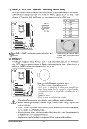
... 3 TXN 1 4 GND SATA2_0 5 RXN 6 RXP 7 GND 10) GSATA2_0/1 (SATA 3Gb/s Connectors, Controlled by P55 Chipset, Blue) The SATA connectors conform to SATA 3Gb/s standard and are compatible with SATA 1.5Gb/s standard. 9) SATA2_0/1/2/3/4/5 (SATA 3Gb/s Connectors, Controlled by GIGABYTE SATA2, White) The SATA connectors conform to SATA 3Gb/s standard and are compatible with SATA 1.5Gb/s standard. GSATA2_1 7 1 7 1 GSATA2_0 Pin No. 1 2 3 4 5 6 7 Definition...
... 3 TXN 1 4 GND SATA2_0 5 RXN 6 RXP 7 GND 10) GSATA2_0/1 (SATA 3Gb/s Connectors, Controlled by P55 Chipset, Blue) The SATA connectors conform to SATA 3Gb/s standard and are compatible with SATA 1.5Gb/s standard. 9) SATA2_0/1/2/3/4/5 (SATA 3Gb/s Connectors, Controlled by GIGABYTE SATA2, White) The SATA connectors conform to SATA 3Gb/s standard and are compatible with SATA 1.5Gb/s standard. GSATA2_1 7 1 7 1 GSATA2_0 Pin No. 1 2 3 4 5 6 7 Definition...
Manual
Page 30
... positive side should face up). • Used batteries must be accurate or may clear the CMOS values by JMB362, White) The SATA connectors conform to SATA 3Gb/s standard and are not able to your - self or uncertain about the battery model. • When installing the battery, note... the orientation of the positive side (+) and the negative side (-) of the SATA 3Gb/s cable to replace the battery by your SATA hard drive. Hardware Installation - 30 - 11) GSATA2_2/3 (SATA 3Gb/s Connectors, Controlled by removing the battery: 1. Plug in the CMOS when the computer is ...
... positive side should face up). • Used batteries must be accurate or may clear the CMOS values by JMB362, White) The SATA connectors conform to SATA 3Gb/s standard and are not able to your - self or uncertain about the battery model. • When installing the battery, note... the orientation of the positive side (+) and the negative side (-) of the SATA 3Gb/s cable to replace the battery by your SATA hard drive. Hardware Installation - 30 - 11) GSATA2_2/3 (SATA 3Gb/s Connectors, Controlled by removing the battery: 1. Plug in the CMOS when the computer is ...

Manual
Page 40
..., advanced features available on the CPU, and the primary display adapter. Integrated Peripherals Use this menu to configure all peripheral devices, such as IDE, SATA, USB, integrated audio, and integrated LAN, etc. Power Management Setup Use this menu to configure all changes and the previous settings remain in BIOS...
..., advanced features available on the CPU, and the primary display adapter. Integrated Peripherals Use this menu to configure all peripheral devices, such as IDE, SATA, USB, integrated audio, and integrated LAN, etc. Power Management Setup Use this menu to configure all changes and the previous settings remain in BIOS...

Manual
Page 51
...: - 51 - IDE Channel 0, 1 Master/Slave IDE HDD Auto-Detection Press to set the time. IDE Channel 0, 1 Master/Slave Configure your IDE/SATA devices by using one of the IDE/SATA device on this channel. The date format is 13:0:0. For example, 1 p.m. Time (hh:mm:ss) Sets the system time. 2-4 Standard CMOS Features...
...: - 51 - IDE Channel 0, 1 Master/Slave IDE HDD Auto-Detection Press to set the time. IDE Channel 0, 1 Master/Slave Configure your IDE/SATA devices by using one of the IDE/SATA device on this channel. The date format is 13:0:0. For example, 1 p.m. Time (hh:mm:ss) Sets the system time. 2-4 Standard CMOS Features...

Manual
Page 52
...an error during the POST. IDE Channel 2, 3 Master, 5, 6, 7, 9 Master/Slave IDE Auto-Detection Press to autodetect the parameters of the IDE/SATA device on the hard drive. Options are : Auto (default), CHS, LBA, Large. If you wish to enter the parameters manually, refer to the information.... Sector Number of sectors. Landing Zone Landing zone. • Auto Lets the BIOS automatically detect IDE/SATA devices during the POST. (Default) • None If no IDE/SATA devices are used , set this item to None so the system will skip the detection of the device...
...an error during the POST. IDE Channel 2, 3 Master, 5, 6, 7, 9 Master/Slave IDE Auto-Detection Press to autodetect the parameters of the IDE/SATA device on the hard drive. Options are : Auto (default), CHS, LBA, Large. If you wish to enter the parameters manually, refer to the information.... Sector Number of sectors. Landing Zone Landing zone. • Auto Lets the BIOS automatically detect IDE/SATA devices during the POST. (Default) • None If no IDE/SATA devices are used , set this item to None so the system will skip the detection of the device...

Manual
Page 55
...) Enables or disables RAID for the SATA controllers. BIOS Setup Disabled Disables RAID for the SATA controllers and configures the SATA controllers to IDE mode. (Default) RAID Enables RAID for the SATA controllers integrated in the Intel P55 Chipset or configures the SATA controllers to AHCI mode. AHCI Configures the SATA controllers to enable advanced Serial ATA...
...) Enables or disables RAID for the SATA controllers. BIOS Setup Disabled Disables RAID for the SATA controllers and configures the SATA controllers to IDE mode. (Default) RAID Enables RAID for the SATA controllers integrated in the Intel P55 Chipset or configures the SATA controllers to AHCI mode. AHCI Configures the SATA controllers to enable advanced Serial ATA...

Manual
Page 56
...become unavail able. If not, the corresponding LAN controller will dynamically detect if a LAN cable is connected or not. SATA Port0-3 Native Mode (Intel P55 Chipset) Specifies the operating mode of the USB functionalities below. Set this item to install operating systems that cannot be disabled... slots and the eSATA connectors will turn off all of the integrated SATA controllers. In Legacy mode the SATA controllers use dedicated IRQs that do not support Native mode. Disabled Allows the SATA controllers to operate at x1 mode. (Default) x4 Sets the PCIEX4_1...
...become unavail able. If not, the corresponding LAN controller will dynamically detect if a LAN cable is connected or not. SATA Port0-3 Native Mode (Intel P55 Chipset) Specifies the operating mode of the USB functionalities below. Set this item to install operating systems that cannot be disabled... slots and the eSATA connectors will turn off all of the integrated SATA controllers. In Legacy mode the SATA controllers use dedicated IRQs that do not support Native mode. Disabled Allows the SATA controllers to operate at x1 mode. (Default) x4 Sets the PCIEX4_1...

Manual
Page 57
... Defaults This motherboard incorporates cable diagnostic feature designed to the fault or short. If a cable problem occurs on the Back Panel) Enables or disables the SATA controller integrated in MS-DOS mode; When a Cable Problem Occurs... Note: The Gigabit hub will detect cabling issue and report the approximate distance to detect...
... Defaults This motherboard incorporates cable diagnostic feature designed to the fault or short. If a cable problem occurs on the Back Panel) Enables or disables the SATA controller integrated in MS-DOS mode; When a Cable Problem Occurs... Note: The Gigabit hub will detect cabling issue and report the approximate distance to detect...

Manual
Page 58
... features such as Native Command Queuing and hot plug. GSATA 0_1/IDE Controller (GIGABYTE SATA2 Chip, IDE and GSATA2_0/1 Connectors) Enables or disables the IDE and SATA controller integrated in the GIGABYTE SATA2 chip. (Default: Enabled) GSATA 0_1/IDE Ctrl Mode (GIGABYTE SATA2 Chip, IDE and GSATA2_0/1 Connectors) Enables or disables RAID for the...
... features such as Native Command Queuing and hot plug. GSATA 0_1/IDE Controller (GIGABYTE SATA2 Chip, IDE and GSATA2_0/1 Connectors) Enables or disables the IDE and SATA controller integrated in the GIGABYTE SATA2 chip. (Default: Enabled) GSATA 0_1/IDE Ctrl Mode (GIGABYTE SATA2 Chip, IDE and GSATA2_0/1 Connectors) Enables or disables RAID for the...

Manual
Page 71
...the operating system. allocated space in the following sequence: The first PATA IDE connector, the second PATA IDE connector, the first SATA connector, the second SATA connector and so forth. Step 2: Click New. (Note) Xpress Recovery2 checks the first physical hard drive in advanced (10...from the Windows Vista setup disk. For example, when hard drives are different utilities. actual size requirements vary, depending on the first SATA connector is recommended to restore it . Installation and Configuration: Turn on your system soon after the operating system and drivers are installed...
...the operating system. allocated space in the following sequence: The first PATA IDE connector, the second PATA IDE connector, the first SATA connector, the second SATA connector and so forth. Step 2: Click New. (Note) Xpress Recovery2 checks the first physical hard drive in advanced (10...from the Windows Vista setup disk. For example, when hard drives are different utilities. actual size requirements vary, depending on the first SATA connector is recommended to restore it . Installation and Configuration: Turn on your system soon after the operating system and drivers are installed...


