
Manual
Page 1
... array to expand its capacity. You can go to the Application Software screen to individually install the X.H.D utility later. Using GIGABYTE eXtreme Hard Drive (X.H.D) Instructions:(Note 2) Before launching X.H.D, make sure the newly added harddrive has equal or greater capacity than... utility only supports the SATA controllers integrated in the array. ) 1. Setting Up a RAID-Ready System Step 1: Configure the system BIOS Enter the system BIOS Setup program, set up all motherboard drivers, including the X.H.D utility. For a RAID 0 array that 's been created earlier, make ...
... array to expand its capacity. You can go to the Application Software screen to individually install the X.H.D utility later. Using GIGABYTE eXtreme Hard Drive (X.H.D) Instructions:(Note 2) Before launching X.H.D, make sure the newly added harddrive has equal or greater capacity than... utility only supports the SATA controllers integrated in the array. ) 1. Setting Up a RAID-Ready System Step 1: Configure the system BIOS Enter the system BIOS Setup program, set up all motherboard drivers, including the X.H.D utility. For a RAID 0 array that 's been created earlier, make ...

Manual
Page 2
Configuring the Smart TPM Utility 18 4.1. Creating a USB Key 18 4.2. Advanced Mode...8 4. Creating a Bluetooth Cell Phone Key 19 4.3. Table of Contents TPM Configuration Procedure 3 1. Installing the Infineon TPM Driver and the Smart TPM Utility 4 2.1. Installing the Infineon TPM Driver 4 2.2. Other Bluetooth Settings 21 4.4. Other Features...21 - 2 - Initializing the TPM chip 5 3.1. Configuring the System BIOS 3 2. Installing the Smart TPM Utility 4 3. Initializing the TPM Chip with the Smart TPM Utility 5 3.2.
Configuring the Smart TPM Utility 18 4.1. Creating a USB Key 18 4.2. Advanced Mode...8 4. Creating a Bluetooth Cell Phone Key 19 4.3. Table of Contents TPM Configuration Procedure 3 1. Installing the Infineon TPM Driver and the Smart TPM Utility 4 2.1. Installing the Infineon TPM Driver 4 2.2. Other Bluetooth Settings 21 4.4. Other Features...21 - 2 - Initializing the TPM chip 5 3.1. Configuring the System BIOS 3 2. Installing the Smart TPM Utility 4 3. Initializing the TPM Chip with the Smart TPM Utility 5 3.2.

Manual
Page 3
... chip. It's recommended that you use the TPM functionality, first enter the system BIOS Setup to back up the encrypted files first. Go to save changes and then exit the BIOS Setup program. CMOS Setup Utility-Copyright (C) 1984-2009 Award Software Security Chip Configuration.... Initializing the TPM chip 4. Step 1: As the computer starts, enter the BIOS Setup program. Configuring the system BIOS 2. Configuring the System BIOS To use the Clear Security Chip setting (press + in the BIOS main menu to display this setting) to Enabled/Activate. Previously encrypted files will ...
... chip. It's recommended that you use the TPM functionality, first enter the system BIOS Setup to back up the encrypted files first. Go to save changes and then exit the BIOS Setup program. CMOS Setup Utility-Copyright (C) 1984-2009 Award Software Security Chip Configuration.... Initializing the TPM chip 4. Step 1: As the computer starts, enter the BIOS Setup program. Configuring the system BIOS 2. Configuring the System BIOS To use the Clear Security Chip setting (press + in the BIOS main menu to display this setting) to Enabled/Activate. Previously encrypted files will ...

Manual
Page 5
... the PSD drive letter, drive label, size, and a local drive on which indicates that is automatically provided. Initializing the TPM chip After configuring the system BIOS and installing the driver software, the Infineon Security Platform icon , which your PSD data when connecting to the instructions in the Infineon Security Platform. 3.1.
... the PSD drive letter, drive label, size, and a local drive on which indicates that is automatically provided. Initializing the TPM chip After configuring the system BIOS and installing the driver software, the Infineon Security Platform icon , which your PSD data when connecting to the instructions in the Infineon Security Platform. 3.1.

Manual
Page 6
... is 4 GB. - 6 - Initialization Procedure of the Infineon Security Platform. To generate a new password, click Generate. 2. To specify the drive label, enter the label in the BIOS Setup program. • This password incorporates the functionalities of the "Owner Password," "User Password," "Emergency Recovery Token Password," and "Password Reset Token Password" of Smart...
... is 4 GB. - 6 - Initialization Procedure of the Infineon Security Platform. To generate a new password, click Generate. 2. To specify the drive label, enter the label in the BIOS Setup program. • This password incorporates the functionalities of the "Owner Password," "User Password," "Emergency Recovery Token Password," and "Password Reset Token Password" of Smart...

Manual
Page 7
Enter a passkey (8~16 digits recommended) in the system BIOS. Before creating a Bluetooth cell phone key, make sure your motherboard includes a Bluetooth receiver and turn on the search and Bluetooth functions on your cell phone. ... of the TPM User Password, your phone. Create a USB key: Select the Use USB storage check box and click Refresh to that you want to BIOS check box will store the encrypted TPM User Password in Passkey which will be used for the USB flash drive(s) that on the left will...
Enter a passkey (8~16 digits recommended) in the system BIOS. Before creating a Bluetooth cell phone key, make sure your motherboard includes a Bluetooth receiver and turn on the search and Bluetooth functions on your cell phone. ... of the TPM User Password, your phone. Create a USB key: Select the Use USB storage check box and click Refresh to that you want to BIOS check box will store the encrypted TPM User Password in Passkey which will be used for the USB flash drive(s) that on the left will...

Manual
Page 18
Configuring the Smart TPM Utility GIGABYTE's unique Smart TPM (Trusted Platform Module) supports the industry's most advanced hardwarebased data encryption. In addition, users can create more than one user uses the "Enable Bacup to BIOS" function to store their PSD data by simply connecting to display the ... or read. • Though the TPM delivers the latest data security technology, it does not guarantee data integrity or provide hardware protection. GIGABYTE is not liable for loss of encrypted data as the portable user key. (If the screen doesn't display the USB flash drive inserted...
Configuring the Smart TPM Utility GIGABYTE's unique Smart TPM (Trusted Platform Module) supports the industry's most advanced hardwarebased data encryption. In addition, users can create more than one user uses the "Enable Bacup to BIOS" function to store their PSD data by simply connecting to display the ... or read. • Though the TPM delivers the latest data security technology, it does not guarantee data integrity or provide hardware protection. GIGABYTE is not liable for loss of encrypted data as the portable user key. (If the screen doesn't display the USB flash drive inserted...

Manual
Page 19
.... Do not turn on the search and Bluetooth functions on the Configure USB Storages tab. When prompted to access/close your PSD by plugging in BIOS Setup and then set earlier and click OK to complete creating the USB key. You are able to confirm, click Yes. Step 3: Enter the TPM...
.... Do not turn on the search and Bluetooth functions on the Configure USB Storages tab. When prompted to access/close your PSD by plugging in BIOS Setup and then set earlier and click OK to complete creating the USB key. You are able to confirm, click Yes. Step 3: Enter the TPM...

Manual
Page 3
..., translated, transmitted, or published in the use GIGABYTE's unique features, read or download the information on/from the Support&Downloads\Motherboard\Technology Guide page on your motherboard revision before updating motherboard BIOS, drivers, or when looking for technical information. ...Documentation Classifications In order to use of the product, read the User's Manual. For example, "REV: 1.0" means the revision of GIGABYTE. For product-related information, check...
..., translated, transmitted, or published in the use GIGABYTE's unique features, read or download the information on/from the Support&Downloads\Motherboard\Technology Guide page on your motherboard revision before updating motherboard BIOS, drivers, or when looking for technical information. ...Documentation Classifications In order to use of the product, read the User's Manual. For example, "REV: 1.0" means the revision of GIGABYTE. For product-related information, check...

Manual
Page 4
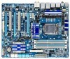
Table of Contents Box Contents...6 Optional Items...6 GA-P55-UD5 Motherboard Layout 7 Block Diagram...8 Chapter 1 Hardware Installation 9 1-1 Installation Precautions 9 1-2 Product Specifications 10 1-3 Installing the CPU and CPU Cooler 13 1-3-1 ...Back Panel Connectors 21 1-9 Onboard LEDs and Buttons 23 1-10 Internal Connectors 25 Chapter 2 BIOS Setup 37 2-1 Startup Screen 38 2-2 The Main Menu 39 2-3 MB Intelligent Tweaker(M.I.T 41 2-4 Standard CMOS Features 51 2-5 Advanced BIOS Features 53 2-6 Integrated Peripherals 55 2-7 Power Management Setup 59 2-8 PC Health Status 61 ...
Table of Contents Box Contents...6 Optional Items...6 GA-P55-UD5 Motherboard Layout 7 Block Diagram...8 Chapter 1 Hardware Installation 9 1-1 Installation Precautions 9 1-2 Product Specifications 10 1-3 Installing the CPU and CPU Cooler 13 1-3-1 ...Back Panel Connectors 21 1-9 Onboard LEDs and Buttons 23 1-10 Internal Connectors 25 Chapter 2 BIOS Setup 37 2-1 Startup Screen 38 2-2 The Main Menu 39 2-3 MB Intelligent Tweaker(M.I.T 41 2-4 Standard CMOS Features 51 2-5 Advanced BIOS Features 53 2-6 Integrated Peripherals 55 2-7 Power Management Setup 59 2-8 PC Health Status 61 ...

Manual
Page 5
... 70 3-7 New Utilities...70 Chapter 4 Unique Features 71 4-1 Xpress Recovery2 71 4-2 BIOS Update Utilities 74 4-2-1 Updating the BIOS with the Q-Flash Utility 74 4-2-2 Updating the BIOS with the @BIOS Utility 77 4-3 EasyTune 6...78 4-4 Dynamic Energy Saver™ 2 79 4-5 Q-Share......81 4-6 Smart 6™ ...82 4-7 Smart TPM ...85 4-8 Teaming ...86 Chapter 5 Appendix...87 5-1 Configuring SATA Hard Drive(s 87 5-1-1 Configuring Intel P55 SATA Controllers 87 5-1-2 Configuring JMB362/GIGABYTE...
... 70 3-7 New Utilities...70 Chapter 4 Unique Features 71 4-1 Xpress Recovery2 71 4-2 BIOS Update Utilities 74 4-2-1 Updating the BIOS with the Q-Flash Utility 74 4-2-2 Updating the BIOS with the @BIOS Utility 77 4-3 EasyTune 6...78 4-4 Dynamic Energy Saver™ 2 79 4-5 Q-Share......81 4-6 Smart 6™ ...82 4-7 Smart TPM ...85 4-8 Teaming ...86 Chapter 5 Appendix...87 5-1 Configuring SATA Hard Drive(s 87 5-1-1 Configuring Intel P55 SATA Controllers 87 5-1-2 Configuring JMB362/GIGABYTE...

Manual
Page 8
... 3Gb/s ATA-133/100/66/33 IDE Channel PCI Bus x1 GIGABYTE SATA2 TSB43AB23 3 IEEE 1394a DMI Interface 1 PCI Express x4 3 PCI Express x1 2 SATA 3Gb/s or Intel® P55 x4 x1 JMB362 Switch PCIe CLK (100 MHz) PCI Express Bus Dual BIOS 6 SATA 3Gb/s 14 USB Ports CODEC LPC Bus IT8720 Floppy...
... 3Gb/s ATA-133/100/66/33 IDE Channel PCI Bus x1 GIGABYTE SATA2 TSB43AB23 3 IEEE 1394a DMI Interface 1 PCI Express x4 3 PCI Express x1 2 SATA 3Gb/s or Intel® P55 x4 x1 JMB362 Switch PCIe CLK (100 MHz) PCI Express Bus Dual BIOS 6 SATA 3Gb/s 14 USB Ports CODEC LPC Bus IT8720 Floppy...
Manual
Page 12
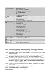
... fan fail warning CPU/System fan speed control (Note 5) 2 x 16 Mbit flash Use of licensed AWARD BIOS Support for DualBIOS™ PnP 1.0a, DMI 2.0, SM BIOS 2.4, ACPI 1.0b Support for @BIOS Support for Q-Flash Support for Xpress BIOS Rescue Support for Download Center Support for Xpress Install Support for Xpress Recovery2 Support for EasyTune...
... fan fail warning CPU/System fan speed control (Note 5) 2 x 16 Mbit flash Use of licensed AWARD BIOS Support for DualBIOS™ PnP 1.0a, DMI 2.0, SM BIOS 2.4, ACPI 1.0b Support for @BIOS Support for Q-Flash Support for Xpress BIOS Rescue Support for Download Center Support for Xpress Install Support for Xpress Recovery2 Support for EasyTune...

Manual
Page 16
It is installed, the BIOS will double the original memory bandwidth. If you begin to prevent hardware damage. • Memory modules have a foolproof design. After the memory is recommended that ... installing the memory in only one DDR3 memory module is recommended that memory of the same capacity, brand, speed, and chips be used . (Go to GIGABYTE's website for the latest memory support list.) • Always turn off the computer and unplug the power cord from the power outlet before installing the...
It is installed, the BIOS will double the original memory bandwidth. If you begin to prevent hardware damage. • Memory modules have a foolproof design. After the memory is recommended that ... installing the memory in only one DDR3 memory module is recommended that memory of the same capacity, brand, speed, and chips be used . (Go to GIGABYTE's website for the latest memory support list.) • Always turn off the computer and unplug the power cord from the power outlet before installing the...

Manual
Page 18
... sure the metal contacts on the slot and then lift the card straight out from the power outlet before you begin to make any required BIOS changes for your operating system. Install the driver provided with your expansion card. • Always turn off the computer and unplug the power... cord from the slot. If necessary, go to BIOS Setup to install an expansion card: • Make sure the motherboard supports the expansion card. PCI Express x1 Slot PCI Express x16 Slot (PCIEX16_1)...
... sure the metal contacts on the slot and then lift the card straight out from the power outlet before you begin to make any required BIOS changes for your operating system. Install the driver provided with your expansion card. • Always turn off the computer and unplug the power... cord from the slot. If necessary, go to BIOS Setup to install an expansion card: • Make sure the motherboard supports the expansion card. PCI Express x1 Slot PCI Express x16 Slot (PCIEX16_1)...
Manual
Page 23
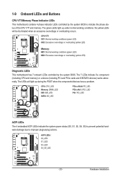
...working conditions (green LED) MD2: Excessive overvoltage or overloading (yellow LED) Diagnostic LEDs This motherboard has 7 onboard LEDs controlled by the system BIOS to improper plug/unplug actions. The 7 LEDs indicate if a component (including CPU and memory) or a device (including PCI and PCIe...works abnormally. 1-9 Onboard LEDs and Buttons CPU VTT/Memory Phase Indicator LEDs This motherboard contains 4 phase indicator LEDs controlled by the system BIOS. The green LEDs light up during the POST when the components/devices have a problem. CPU: CPU_LED Memory: DIMM_LED IDE: IDE_LED ...
...working conditions (green LED) MD2: Excessive overvoltage or overloading (yellow LED) Diagnostic LEDs This motherboard has 7 onboard LEDs controlled by the system BIOS to improper plug/unplug actions. The 7 LEDs indicate if a component (including CPU and memory) or a device (including PCI and PCIe...works abnormally. 1-9 Onboard LEDs and Buttons CPU VTT/Memory Phase Indicator LEDs This motherboard contains 4 phase indicator LEDs controlled by the system BIOS. The green LEDs light up during the POST when the components/devices have a problem. CPU: CPU_LED Memory: DIMM_LED IDE: IDE_LED ...

Manual
Page 24
...want to change hardware components or conduct hardware testing. PHASE LED The PHASE LEDs indicate the CPU loading. Refer to Chapter 2, "BIOS Setup," for more the number of lighted LEDs. PW_SW: Power button RST_SW: Reset button CMOS_SW: Clearing CMOS button • ...8226; After system restart, go to BIOS Setup to load factory defaults (select Load Optimized Defaults) or manually configure the BIOS settings (refer to Chapter 4, "Dynamic Energy Saver™ 2," for BIOS configurations). Hardware Installation - 24 - date information and BIOS configurations) and reset the CMOS values ...
...want to change hardware components or conduct hardware testing. PHASE LED The PHASE LEDs indicate the CPU loading. Refer to Chapter 2, "BIOS Setup," for more the number of lighted LEDs. PW_SW: Power button RST_SW: Reset button CMOS_SW: Clearing CMOS button • ...8226; After system restart, go to BIOS Setup to load factory defaults (select Load Optimized Defaults) or manually configure the BIOS settings (refer to Chapter 4, "Dynamic Energy Saver™ 2," for BIOS configurations). Hardware Installation - 24 - date information and BIOS configurations) and reset the CMOS values ...
Manual
Page 30
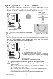
... the positive and negative terminals of the SATA 3Gb/s cable to your SATA hard drive. The battery provides power to keep the values (such as BIOS configurations, date, and time information) in the CMOS when the computer is replaced with an incorrect model. • Contact the place of the battery (the...
... the positive and negative terminals of the SATA 3Gb/s cable to your SATA hard drive. The battery provides power to keep the values (such as BIOS configurations, date, and time information) in the CMOS when the computer is replaced with an incorrect model. • Contact the place of the battery (the...
Manual
Page 31
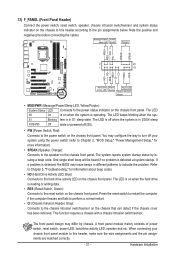
... when the sys- The front panel design may differ by issuing a beep code. When connecting your system using the power switch (refer to Chapter 2, "BIOS Setup," "Power Management Setup," for information about beep codes. • HD (Hard Drive Activity LED, Blue) Connects to the hard drive activity LED on... the chassis front panel. The LED is off when the system is detected, the BIOS may configure the way to turn off (S5). • PW (Power Switch, Red): Connects to the power switch on the chassis front panel. If...
... when the sys- The front panel design may differ by issuing a beep code. When connecting your system using the power switch (refer to Chapter 2, "BIOS Setup," "Power Management Setup," for information about beep codes. • HD (Hard Drive Activity LED, Blue) Connects to the hard drive activity LED on... the chassis front panel. The LED is off when the system is detected, the BIOS may configure the way to turn off (S5). • PW (Power Switch, Red): Connects to the power switch on the chassis front panel. If...

Manual
Page 37
... program, press the key during system startup, saving system parameters and loading operating system, etc. To upgrade the BIOS, use either the GIGABYTE Q-Flash or @BIOS utility. • Q-Flash allows the user to activate certain system features. When the power is a Windows-based utility that allows the user to modify basic ...
... program, press the key during system startup, saving system parameters and loading operating system, etc. To upgrade the BIOS, use either the GIGABYTE Q-Flash or @BIOS utility. • Q-Flash allows the user to activate certain system features. When the power is a Windows-based utility that allows the user to modify basic ...


