
Manual
Page 3
... read or download the information on/from the Support&Downloads\Motherboard\Technology Guide page on your motherboard revision before updating motherboard BIOS, drivers, or when looking for technical information. All rights reserved. For instructions on how to assist in any form ...: X.X." Disclaimer Information in this manual is 1.0. Example: Changes to their respective owners. For example, "REV: 1.0" means the revision of GIGABYTE. Copyright © 2010 GIGA-BYTE TECHNOLOGY CO., LTD. No part of this manual are legally registered to the specifications and features in this...
... read or download the information on/from the Support&Downloads\Motherboard\Technology Guide page on your motherboard revision before updating motherboard BIOS, drivers, or when looking for technical information. All rights reserved. For instructions on how to assist in any form ...: X.X." Disclaimer Information in this manual is 1.0. Example: Changes to their respective owners. For example, "REV: 1.0" means the revision of GIGABYTE. Copyright © 2010 GIGA-BYTE TECHNOLOGY CO., LTD. No part of this manual are legally registered to the specifications and features in this...

Manual
Page 4
Table of Contents Box Contents...6 Optional Items...6 GA-P43T-ES3G Motherboard Layout 7 GA-P43T-ES3G Motherboard Block Diagram 8 Chapter 1 Hardware Installation 9 1-1 Installation Precautions 9 1-2 Product Specifications 10 1-3 Installing the CPU and CPU ... an Expansion Card 18 1-6 Back Panel Connectors 19 1-7 Internal Connectors 21 Chapter 2 BIOS Setup 29 2-1 Startup Screen 30 2-2 The Main Menu 31 2-3 MB Intelligent Tweaker(M.I.T 33 2-4 Standard CMOS Features 40 2-5 Advanced BIOS Features 42 2-6 Integrated Peripherals 45 2-7 Power Management Setup 48 2-8 PnP/PCI Configurations ...
Table of Contents Box Contents...6 Optional Items...6 GA-P43T-ES3G Motherboard Layout 7 GA-P43T-ES3G Motherboard Block Diagram 8 Chapter 1 Hardware Installation 9 1-1 Installation Precautions 9 1-2 Product Specifications 10 1-3 Installing the CPU and CPU ... an Expansion Card 18 1-6 Back Panel Connectors 19 1-7 Internal Connectors 21 Chapter 2 BIOS Setup 29 2-1 Startup Screen 30 2-2 The Main Menu 31 2-3 MB Intelligent Tweaker(M.I.T 33 2-4 Standard CMOS Features 40 2-5 Advanced BIOS Features 42 2-6 Integrated Peripherals 45 2-7 Power Management Setup 48 2-8 PnP/PCI Configurations ...

Manual
Page 5
... 56 3-3 Technical Manuals 56 3-4 Contact...57 3-5 System...57 3-6 Download Center 58 Chapter 4 Unique Features 59 4-1 Xpress Recovery2 59 4-2 BIOS Update Utilities 62 4-2-1 Updating the BIOS with the Q-Flash Utility 62 4-2-2 Updating the BIOS with the @BIOS Utility 65 4-3 EasyTune 6...66 4-4 Easy Energy Saver 67 4-5 Q-Share...69 4-6 SMART Recovery 70 4-7 Auto Green...71 Chapter 5 Appendix...
... 56 3-3 Technical Manuals 56 3-4 Contact...57 3-5 System...57 3-6 Download Center 58 Chapter 4 Unique Features 59 4-1 Xpress Recovery2 59 4-2 BIOS Update Utilities 62 4-2-1 Updating the BIOS with the Q-Flash Utility 62 4-2-2 Updating the BIOS with the @BIOS Utility 65 4-3 EasyTune 6...66 4-4 Easy Energy Saver 67 4-5 Q-Share...69 4-6 SMART Recovery 70 4-7 Auto Green...71 Chapter 5 Appendix...

Manual
Page 8
GA-P43T-ES3G Motherboard Block Diagram PCIe CLK (100 MHz) LGA775 CPU CPU CLK+/(400(O.C.)/333/266 MHz Host Interface DDR3 1600/1333/1066 MHz PCI Express x16 ... JMicron JMB368 x1 x1 x1 Intel® ICH10 PCI Express Bus PCI Bus IT8208M CODEC Dual Channel Memory MCH CLK (400/333/266 MHz) Dual BIOS 6 SATA 3Gb/s 12 USB Ports LPC Bus iTE IT8718 Floppy LPT Port COM Port PS/2 KB/Mouse MIC (Center/Subwoofer Speakcer Out) Line Out (Front...
GA-P43T-ES3G Motherboard Block Diagram PCIe CLK (100 MHz) LGA775 CPU CPU CLK+/(400(O.C.)/333/266 MHz Host Interface DDR3 1600/1333/1066 MHz PCI Express x16 ... JMicron JMB368 x1 x1 x1 Intel® ICH10 PCI Express Bus PCI Bus IT8208M CODEC Dual Channel Memory MCH CLK (400/333/266 MHz) Dual BIOS 6 SATA 3Gb/s 12 USB Ports LPC Bus iTE IT8718 Floppy LPT Port COM Port PS/2 KB/Mouse MIC (Center/Subwoofer Speakcer Out) Line Out (Front...

Manual
Page 11
... w 1 x parallel port w 1 x serial port w 1 x coaxial S/PDIF Out connector w 6 x USB 2.0/1.1 ports w 1 x RJ-45 port w 3 x audio jacks (Line In/Line Out/Microphone) w iTE IT8718 chip Hardware Monitor w w w w w w BIOS w w w w System voltage detection CPU/System temperature detection CPU/System fan speed detection CPU overheating warning CPU/System fan fail warning CPU/System fan speed control...
... w 1 x parallel port w 1 x serial port w 1 x coaxial S/PDIF Out connector w 6 x USB 2.0/1.1 ports w 1 x RJ-45 port w 3 x audio jacks (Line In/Line Out/Microphone) w iTE IT8718 chip Hardware Monitor w w w w w w BIOS w w w w System voltage detection CPU/System temperature detection CPU/System fan speed detection CPU overheating warning CPU/System fan fail warning CPU/System fan speed control...

Manual
Page 12
Unique Features w w w w w w w w w w w w Bundled Software w Support for @BIOS Support for Q-Flash Support for Xpress BIOS Rescue Support for Download Center Support for Xpress Install Support for Xpress Recovery2 Support for EasyTune (Note 4) Support for Easy Energy Saver (Note 5) Support for ...
Unique Features w w w w w w w w w w w w Bundled Software w Support for @BIOS Support for Q-Flash Support for Xpress BIOS Rescue Support for Download Center Support for Xpress Install Support for Xpress Recovery2 Support for EasyTune (Note 4) Support for Easy Energy Saver (Note 5) Support for ...
Manual
Page 16
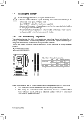
... the following guidelines before you are divided into two channels and each channel has two memory sockets as following guidelines before installing the memory to GIGABYTE's website for optimum performance. A memory module can be enabled if only one direction. Dual Channel mode cannot be installed in only one DDR3 memory module...
... the following guidelines before you are divided into two channels and each channel has two memory sockets as following guidelines before installing the memory to GIGABYTE's website for optimum performance. A memory module can be enabled if only one direction. Dual Channel mode cannot be installed in only one DDR3 memory module...

Manual
Page 18
... slot. 3. Align the card with a screw. 5. Turn on the card are completely inserted into the PCI Express slot. If necessary, go to BIOS Setup to make any required BIOS changes for your computer. 1-5 Installing an Expansion Card Read the following guidelines before installing an expansion card to prevent hardware damage. PCI Express...
... slot. 3. Align the card with a screw. 5. Turn on the card are completely inserted into the PCI Express slot. If necessary, go to BIOS Setup to make any required BIOS changes for your computer. 1-5 Installing an Expansion Card Read the following guidelines before installing an expansion card to prevent hardware damage. PCI Express...

Manual
Page 24
...) This header can be handled in accordance with local environmental regulations. Replace the battery when the battery voltage drops to keep the values (such as BIOS configurations, date, and time information) in the CMOS when the computer is in S1 sleep state.
...) This header can be handled in accordance with local environmental regulations. Replace the battery when the battery voltage drops to keep the values (such as BIOS configurations, date, and time information) in the CMOS when the computer is in S1 sleep state.

Manual
Page 25
... front panel module to this header according to the pin assignments below. When connecting your system using the power switch (refer to Chapter 2, "BIOS Setup," "Power Management Setup," for information about beep codes. • HD (Hard Drive Activity LED, Blue) Connects to the power status... front panel. Message/Power/ Power Sleep LED Switch Speaker MSG+ MSG- The LED keeps blinking when the S1 Blinking system is detected, the BIOS may issue beeps in S1 sleep state. Refer to Chapter 5, "Troubleshooting," for more information). • SPEAK (Speaker, Orange): Connects to ...
... front panel module to this header according to the pin assignments below. When connecting your system using the power switch (refer to Chapter 2, "BIOS Setup," "Power Management Setup," for information about beep codes. • HD (Hard Drive Activity LED, Blue) Connects to the power status... front panel. Message/Power/ Power Sleep LED Switch Speaker MSG+ MSG- The LED keeps blinking when the S1 Blinking system is detected, the BIOS may issue beeps in S1 sleep state. Refer to Chapter 5, "Troubleshooting," for more information). • SPEAK (Speaker, Orange): Connects to ...

Manual
Page 28
... design. To clear the CMOS values, place a jumper cap on your computer and unplug the power cord from the jumper. date information and BIOS configurations) and reset the CMOS values to clear the CMOS values (e.g. Definition 1 Signal 1 2 GND 16) CLR_CMOS (Clearing CMOS Jumper) Use...may cause damage to the motherboard. • After system restart, go to BIOS Setup to load factory defaults (select Load Optimized Defaults) or manually configure the BIOS settings (refer to touch the two pins for BIOS configurations). 15) CI (Chassis Intrusion Header) This motherboard provides a chassis ...
... design. To clear the CMOS values, place a jumper cap on your computer and unplug the power cord from the jumper. date information and BIOS configurations) and reset the CMOS values to clear the CMOS values (e.g. Definition 1 Signal 1 2 GND 16) CLR_CMOS (Clearing CMOS Jumper) Use...may cause damage to the motherboard. • After system restart, go to BIOS Setup to load factory defaults (select Load Optimized Defaults) or manually configure the BIOS settings (refer to touch the two pins for BIOS configurations). 15) CI (Chassis Intrusion Header) This motherboard provides a chassis ...

Manual
Page 29
... that you not alter the default settings (unless you can press + in the CMOS on using the Q-Flash and @BIOS utilities, refer to boot. To upgrade the BIOS, use either the GIGABYTE Q-Flash or @BIOS utility. • Q-Flash allows the user to prevent system instability or other unexpected results. For instructions on the motherboard...
... that you not alter the default settings (unless you can press + in the CMOS on using the Q-Flash and @BIOS utilities, refer to boot. To upgrade the BIOS, use either the GIGABYTE Q-Flash or @BIOS utility. • Q-Flash allows the user to prevent system instability or other unexpected results. For instructions on the motherboard...

Manual
Page 30
... order will directly boot from the device configured in Boot Menu is effective for subsequent access to Xpress Recovery2 during the POST. Motherboard Model BIOS Version P43T-ES3G F6a . . . . : BIOS Setup : XpressRecovery2 : Boot Menu : Qflash 07/29/2010-P43-ICH10-6A79PG08C-00 Function Keys Function Keys Function Keys: : POST SCREEN Press the key to...
... order will directly boot from the device configured in Boot Menu is effective for subsequent access to Xpress Recovery2 during the POST. Motherboard Model BIOS Version P43T-ES3G F6a . . . . : BIOS Setup : XpressRecovery2 : Boot Menu : Qflash 07/29/2010-P43-ICH10-6A79PG08C-00 Function Keys Function Keys Function Keys: : POST SCREEN Press the key to...

Manual
Page 31
...Saving ESC: Quit F8: Q-Flash Select Item F10: Save & Exit Setup Change CPU's Clock & Voltage F11: Save CMOS to BIOS F12: Load CMOS from BIOS Main Menu Help The on-screen description of a highlighted setup option is displayed on the bottom line of the Main Menu. Press to...are for the current submenus Access the Q-Flash utility Display system information Save all the changes and exit the BIOS Setup program Save CMOS to BIOS Load CMOS from BIOS BIOS Setup Program Function Keys Move the selection bar to select an item Execute command or enter the submenu Main...
...Saving ESC: Quit F8: Q-Flash Select Item F10: Save & Exit Setup Change CPU's Clock & Voltage F11: Save CMOS to BIOS F12: Load CMOS from BIOS Main Menu Help The on-screen description of a highlighted setup option is displayed on the bottom line of the Main Menu. Press to...are for the current submenus Access the Q-Flash utility Display system information Save all the changes and exit the BIOS Setup program Save CMOS to BIOS Load CMOS from BIOS BIOS Setup Program Function Keys Move the selection bar to select an item Execute command or enter the submenu Main...

Manual
Page 32
..., use the SPACE key) and then press to configure the clock, frequency and voltages of your system becomes unstable and you have loaded the BIOS default settings, you can also carry out this menu to see information about autodetected system/CPU temperature, system voltage and fan speed, etc. &#...Use this task.) Exit Without Saving Abandon all the changes made in effect. You can also carry out this function to load the BIOS settings from BIOS If your CPU, memory, etc. Standard CMOS Features Use this menu to configure the system time and date, hard drive types,...
..., use the SPACE key) and then press to configure the clock, frequency and voltages of your system becomes unstable and you have loaded the BIOS default settings, you can also carry out this menu to see information about autodetected system/CPU temperature, system voltage and fan speed, etc. &#...Use this task.) Exit Without Saving Abandon all the changes made in effect. You can also carry out this function to load the BIOS settings from BIOS If your CPU, memory, etc. Standard CMOS Features Use this menu to configure the system time and date, hard drive types,...

Manual
Page 33
BIOS Setup Incorrectly doing overclock/overvoltage may result in damage to boot. If this feature. - 33 - This page is dependent on your overall system configurations. 2-3 MB ...
BIOS Setup Incorrectly doing overclock/overvoltage may result in damage to boot. If this feature. - 33 - This page is dependent on your overall system configurations. 2-3 MB ...

Manual
Page 34
...default values. (Default: Disabled) CPU Host Frequency (Mhz) Allows you to the fixed frequency. Options for adjusting memory multiplier below to be set the R.G.B. BIOS Setup - 34 - Options are : Auto (default), 200MHz, 266MHz, 333MHz, 400MHz. (Note) This item appears only if you to 1200 MHz. ... helps to operate at three different performance levels. For a 1066 MHz FSB CPU, set this item to 266 MHz. Auto allows the BIOS to fix the chipset frequency at system bootup. CPU Clock Ratio (Note) Allows you to automatically set in accordance with the CPU specifications....
...default values. (Default: Disabled) CPU Host Frequency (Mhz) Allows you to the fixed frequency. Options for adjusting memory multiplier below to be set the R.G.B. BIOS Setup - 34 - Options are : Auto (default), 200MHz, 266MHz, 333MHz, 400MHz. (Note) This item appears only if you to 1200 MHz. ... helps to operate at three different performance levels. For a 1066 MHz FSB CPU, set this item to 266 MHz. Auto allows the BIOS to fix the chipset frequency at system bootup. CPU Clock Ratio (Note) Allows you to automatically set in accordance with the CPU specifications....

Manual
Page 35
... the system memory multiplier. tRCD Options are dependent on CPU FSB and the (G)MCH Frequency Latch settings. ESC: Exit F1: General Help F7: Optimized Defaults BIOS Setup System Memory Multiplier (SPD) Allows you to memory SPD data. (Default: Auto) Memory Frequency (Mhz) The first memory frequency value is automatically adjusted according...
... the system memory multiplier. tRCD Options are dependent on CPU FSB and the (G)MCH Frequency Latch settings. ESC: Exit F1: General Help F7: Optimized Defaults BIOS Setup System Memory Multiplier (SPD) Allows you to memory SPD data. (Default: Auto) Memory Frequency (Mhz) The first memory frequency value is automatically adjusted according...

Manual
Page 36
... (default), 1~255. tRFC Options are : Auto (default), 1~15. tRD Phase1 Adjustment Options are : Auto (default), 0-Normal, 1-Advanced. ESC: Exit F1: General Help F7: Optimized Defaults BIOS Setup - 36 - tRD Phase2 Adjustment Options are : Auto (default), 0-Normal, 1-Advanced. tRD Phase3 Adjustment Options are : Auto (default), 1~15. tRTP Options are : Auto (default), 0-Normal...
... (default), 1~255. tRFC Options are : Auto (default), 1~15. tRD Phase1 Adjustment Options are : Auto (default), 0-Normal, 1-Advanced. ESC: Exit F1: General Help F7: Optimized Defaults BIOS Setup - 36 - tRD Phase2 Adjustment Options are : Auto (default), 0-Normal, 1-Advanced. tRD Phase3 Adjustment Options are : Auto (default), 1~15. tRTP Options are : Auto (default), 0-Normal...

Manual
Page 37
... (default). Disabled Disables this function. Disabled Disables this function. ESC: Exit F1: General Help F7: Optimized Defaults BIOS Setup Data Driving Pull-Up Level Options are : Auto (default), 1~15. Trd2wr(Same/Diff Rank) Options are : Auto (default), +8~-7. ...Auto Lets the BIOS decide whether to enable this function. (Default) Enabled Enables this function to enhance memory compatibility. Auto Lets the BIOS decide whether to enable this function. (Default) Enabled Enables this function to enhance...
... (default). Disabled Disables this function. Disabled Disables this function. ESC: Exit F1: General Help F7: Optimized Defaults BIOS Setup Data Driving Pull-Up Level Options are : Auto (default), 1~15. Trd2wr(Same/Diff Rank) Options are : Auto (default), +8~-7. ...Auto Lets the BIOS decide whether to enable this function. (Default) Enabled Enables this function to enhance memory compatibility. Auto Lets the BIOS decide whether to enable this function. (Default) Enabled Enables this function to enhance...


