Manual
Page 3
...and features in this manual may be made by copyright laws and is the property of the motherboard is protected by GIGABYTE without GIGABYTE's prior written permission. Example: For detailed product information, carefully read or download the information on/from the Support&...Downloads\Motherboard\Technology Guide page on your motherboard revision before updating motherboard BIOS, drivers, or when looking for technical information. Changes to use of this product, GIGABYTE provides the following types of documentations: For quick set-up of this : "REV:...
...and features in this manual may be made by copyright laws and is the property of the motherboard is protected by GIGABYTE without GIGABYTE's prior written permission. Example: For detailed product information, carefully read or download the information on/from the Support&...Downloads\Motherboard\Technology Guide page on your motherboard revision before updating motherboard BIOS, drivers, or when looking for technical information. Changes to use of this product, GIGABYTE provides the following types of documentations: For quick set-up of this : "REV:...
Manual
Page 4
Table of Contents Box Contents...6 Optional Items...6 GA-P41-ES3G Motherboard Layout 7 Block Diagram...8 Chapter 1 Hardware Installation 9 1-1 Installation Precautions 9 1-2 Product Specifications 10 1-3 Installing the CPU and CPU Cooler ...1-5 Installing an Expansion Card 18 1-6 Back Panel Connectors 19 1-7 Internal Connectors 21 Chapter 2 BIOS Setup 29 2-1 Startup Screen 30 2-2 The Main Menu 31 2-3 MB Intelligent Tweaker(M.I.T 33 2-4 Standard CMOS Features 40 2-5 Advanced BIOS Features 42 2-6 Integrated Peripherals 45 2-7 Power Management Setup 48 2-8 PnP/PCI Configurations 50 ...
Table of Contents Box Contents...6 Optional Items...6 GA-P41-ES3G Motherboard Layout 7 Block Diagram...8 Chapter 1 Hardware Installation 9 1-1 Installation Precautions 9 1-2 Product Specifications 10 1-3 Installing the CPU and CPU Cooler ...1-5 Installing an Expansion Card 18 1-6 Back Panel Connectors 19 1-7 Internal Connectors 21 Chapter 2 BIOS Setup 29 2-1 Startup Screen 30 2-2 The Main Menu 31 2-3 MB Intelligent Tweaker(M.I.T 33 2-4 Standard CMOS Features 40 2-5 Advanced BIOS Features 42 2-6 Integrated Peripherals 45 2-7 Power Management Setup 48 2-8 PnP/PCI Configurations 50 ...
Manual
Page 5
... 56 3-3 Technical Manuals 56 3-4 Contact...57 3-5 System...57 3-6 Download Center 58 Chapter 4 Unique Features 59 4-1 Xpress Recovery2 59 4-2 BIOS Update Utilities 62 4-2-1 Updating the BIOS with the Q-Flash Utility 62 4-2-2 Updating the BIOS with the @BIOS Utility 65 4-3 EasyTune 6...66 4-4 Easy Energy Saver 67 4-5 Q-Share...69 4-6 SMART Recovery 70 Chapter 5 Appendix...71 5-1-1 Configuring 2/4/5.1/7.1-Channel...
... 56 3-3 Technical Manuals 56 3-4 Contact...57 3-5 System...57 3-6 Download Center 58 Chapter 4 Unique Features 59 4-1 Xpress Recovery2 59 4-2 BIOS Update Utilities 62 4-2-1 Updating the BIOS with the Q-Flash Utility 62 4-2-2 Updating the BIOS with the @BIOS Utility 65 4-3 EasyTune 6...66 4-4 Easy Energy Saver 67 4-5 Q-Share...69 4-6 SMART Recovery 70 Chapter 5 Appendix...71 5-1-1 Configuring 2/4/5.1/7.1-Channel...
Manual
Page 8
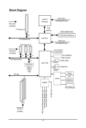
Block Diagram PCIe CLK (100 MHz) 1 PCI Express x16 x16 PCI Express x16 3 PCI Express x1 PCIe CLK (100 MHz) x1 x1 x1 PCI Express Bus x1 RTL8111D RJ45 LAN PCI Bus LGA775 Processor CPU CLK+/(333/266/200 MHz) Host Interface Intel® G41 DDR2 800/667 MHz Dual Channel Memory MCH CLK (333/266/200 MHz) Intel® ICH7 CODEC Dual BIOS ATA-100/66/33 IDE Channel 4 SATA 3Gb/s 8 USB Ports IT8718 Floppy LPT COM Port PS/2 KB/Mouse MIC (Center/Subwoofer Speaker Out) Line-Out (Front Speaker Out) Line-In (Rear Speaker Out) S/ PDIF Out 3 PCI PCI CLK (33 MHz) - 8 -
Block Diagram PCIe CLK (100 MHz) 1 PCI Express x16 x16 PCI Express x16 3 PCI Express x1 PCIe CLK (100 MHz) x1 x1 x1 PCI Express Bus x1 RTL8111D RJ45 LAN PCI Bus LGA775 Processor CPU CLK+/(333/266/200 MHz) Host Interface Intel® G41 DDR2 800/667 MHz Dual Channel Memory MCH CLK (333/266/200 MHz) Intel® ICH7 CODEC Dual BIOS ATA-100/66/33 IDE Channel 4 SATA 3Gb/s 8 USB Ports IT8718 Floppy LPT COM Port PS/2 KB/Mouse MIC (Center/Subwoofer Speaker Out) Line-Out (Front Speaker Out) Line-In (Rear Speaker Out) S/ PDIF Out 3 PCI PCI CLK (33 MHz) - 8 -
Manual
Page 11
... port w 1 x serial port w 1 x coaxial S/PDIF Out connector w 4 x USB 2.0/1.1 ports w 1 x RJ-45 port w 3 x audio jacks (Line In/Line Out/Microphone) I/O Controller w iTE IT8718 chip Hardware Monitor w w w w w w BIOS w w w w System voltage detection CPU/System temperature detection CPU/System/Power fan speed detection CPU overheating warning CPU/System/Power fan fail warning CPU fan speed...
... port w 1 x serial port w 1 x coaxial S/PDIF Out connector w 4 x USB 2.0/1.1 ports w 1 x RJ-45 port w 3 x audio jacks (Line In/Line Out/Microphone) I/O Controller w iTE IT8718 chip Hardware Monitor w w w w w w BIOS w w w w System voltage detection CPU/System temperature detection CPU/System/Power fan speed detection CPU overheating warning CPU/System/Power fan fail warning CPU fan speed...
Manual
Page 12
For example, 4 GB of memory is reserved for Easy Energy Saver. Hardware Installation - 12 - Unique Features w w w w w w w w w w Bundled Software w Support for @BIOS Support for Q-Flash Support for Xpress BIOS Rescue Support for Download Center Support for Xpress Install Support for Xpress Recovery2 Support for EasyTune (Note 4) Support for Easy Energy Saver (Note 5) Support for...
For example, 4 GB of memory is reserved for Easy Energy Saver. Hardware Installation - 12 - Unique Features w w w w w w w w w w Bundled Software w Support for @BIOS Support for Q-Flash Support for Xpress BIOS Rescue Support for Download Center Support for Xpress Install Support for Xpress Recovery2 Support for EasyTune (Note 4) Support for Easy Energy Saver (Note 5) Support for...
Manual
Page 16
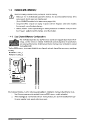
...in Dual Channel mode. 1. It is recommended that memory of the same capacity, brand, speed, and chips be used . (Go to GIGABYTE's website for the latest memory support list.) • Always turn off the computer and unplug the power cord from the power outlet before ...enabling Dual Channel mode with two memory modules, it is recommended that the motherboard supports the memory. After the memory is installed, the BIOS will double the original memory bandwidth. Hardware Installation - 16 - Enabling Dual Channel memory mode will automatically detect the specifications and capacity of...
...in Dual Channel mode. 1. It is recommended that memory of the same capacity, brand, speed, and chips be used . (Go to GIGABYTE's website for the latest memory support list.) • Always turn off the computer and unplug the power cord from the power outlet before ...enabling Dual Channel mode with two memory modules, it is recommended that the motherboard supports the memory. After the memory is installed, the BIOS will double the original memory bandwidth. Hardware Installation - 16 - Enabling Dual Channel memory mode will automatically detect the specifications and capacity of...
Manual
Page 18
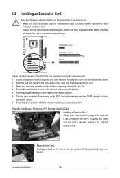
... slot. Carefully read the manual that supports your card. Make sure the metal contacts on your computer. If necessary, go to BIOS Setup to prevent hardware damage. Hardware Installation - 18 - Secure the card's metal bracket to correctly install your expansion card in your...motherboard supports the expansion card. 1-5 Installing an Expansion Card Read the following guidelines before installing an expansion card to make any required BIOS changes for your expansion card(s). 7. Locate an expansion slot that came with the expansion card in the expansion slot. 1. Make ...
... slot. Carefully read the manual that supports your card. Make sure the metal contacts on your computer. If necessary, go to BIOS Setup to prevent hardware damage. Hardware Installation - 18 - Secure the card's metal bracket to correctly install your expansion card in your...motherboard supports the expansion card. 1-5 Installing an Expansion Card Read the following guidelines before installing an expansion card to make any required BIOS changes for your expansion card(s). 7. Locate an expansion slot that came with the expansion card in the expansion slot. 1. Make ...
Manual
Page 25
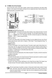
... on the chassis front panel. If a problem is on the chassis front panel. When connecting your system using the power switch (refer to Chapter 2, "BIOS Setup," "Power Management Setup," for information about beep codes. • HD (Hard Drive Activity LED) Connects to the hard drive activity LED on the ...chassis front panel. Hardware Installation The LED S0 On is detected, the BIOS may issue beeps in S3/S4 sleep S3/S4/S5 Off state or powered off your chassis front panel module to this header according to...
... on the chassis front panel. If a problem is on the chassis front panel. When connecting your system using the power switch (refer to Chapter 2, "BIOS Setup," "Power Management Setup," for information about beep codes. • HD (Hard Drive Activity LED) Connects to the hard drive activity LED on the ...chassis front panel. Hardware Installation The LED S0 On is detected, the BIOS may issue beeps in S3/S4 sleep S3/S4/S5 Off state or powered off your chassis front panel module to this header according to...
Manual
Page 28
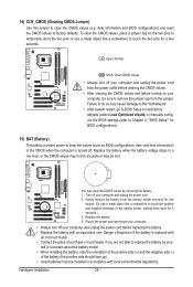
To clear the CMOS values, place a jumper cap on your computer, be sure to keep the values (such as BIOS configurations, date, and time information) in the CMOS when the computer is replaced with an incorrect model. • Contact the place of purchase or ...so may be accurate or may cause damage to the motherboard. • After system restart, go to BIOS Setup to load factory defaults (select Load Optimized efaults) or manually configure the BIOS settings (refer to Chapter 2, "BIOS Setup," for one . Hardware Installation - 28 - Gently remove the battery from the battery holder and ...
To clear the CMOS values, place a jumper cap on your computer, be sure to keep the values (such as BIOS configurations, date, and time information) in the CMOS when the computer is replaced with an incorrect model. • Contact the place of purchase or ...so may be accurate or may cause damage to the motherboard. • After system restart, go to BIOS Setup to load factory defaults (select Load Optimized efaults) or manually configure the BIOS settings (refer to Chapter 2, "BIOS Setup," for one . Hardware Installation - 28 - Gently remove the battery from the battery holder and ...
Manual
Page 29
..." section in the CMOS on the motherboard supplies the necessary power to the CMOS to boot. If this chapter or introductions of BIOS from the Internet and updates the BIOS. To upgrade the BIOS, use either the GIGABYTE Q-Flash or @BIOS utility. • Q-Flash allows the user to quickly and easily upgrade or back up...
..." section in the CMOS on the motherboard supplies the necessary power to the CMOS to boot. If this chapter or introductions of BIOS from the Internet and updates the BIOS. To upgrade the BIOS, use either the GIGABYTE Q-Flash or @BIOS utility. • Q-Flash allows the user to quickly and easily upgrade or back up...
Manual
Page 30
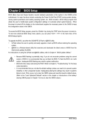
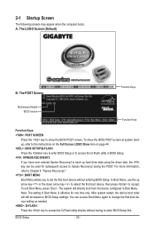
... subsequent access to Xpress Recovery2 during the POST. The POST Screen Award Modular BIOS v6.00PG, An Energy Star Ally Copyright (C) 1984-2009, Award Software, Inc. To show the BIOS POST screen. A. The LOGO Screen (Default) B. Motherboard Model BIOS Version P41-ES3G E8 . . . . : BIOS Setup : XpressRecovery2 : Boot Menu : Qflash 09/14/2009-G41-ICH7-6A79PG06C-00...
... subsequent access to Xpress Recovery2 during the POST. The POST Screen Award Modular BIOS v6.00PG, An Energy Star Ally Copyright (C) 1984-2009, Award Software, Inc. To show the BIOS POST screen. A. The LOGO Screen (Default) B. Motherboard Model BIOS Version P41-ES3G E8 . . . . : BIOS Setup : XpressRecovery2 : Boot Menu : Qflash 09/14/2009-G41-ICH7-6A79PG06C-00...
Manual
Page 31
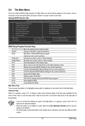
...chapter are for the current submenus Access the Q-Flash utility Display system information Save all the changes and exit the BIOS Setup program Save CMOS to its defaults. • The BIOS Setup menus described in the Main Menu or a submenu, press + to access more advanced options. • ...Without Saving ESC: Quit F8: Q-Flash Select Item F10: Save & Exit Setup Change CPU's Clock & Voltage F11: Save CMOS to BIOS F12: Load CMOS from BIOS Main Menu Help The on-screen description of a highlighted setup option is not stable as shown below) appears on the bottom line of...
...chapter are for the current submenus Access the Q-Flash utility Display system information Save all the changes and exit the BIOS Setup program Save CMOS to its defaults. • The BIOS Setup menus described in the Main Menu or a submenu, press + to access more advanced options. • ...Without Saving ESC: Quit F8: Q-Flash Select Item F10: Save & Exit Setup Change CPU's Clock & Voltage F11: Save CMOS to BIOS F12: Load CMOS from BIOS Main Menu Help The on-screen description of a highlighted setup option is not stable as shown below) appears on the bottom line of...
Manual
Page 32
...but not to make changes in effect. First enter the profile name (to erase the default profile name, use this function to load the BIOS settings from BIOS If your CPU, memory, etc. Standard CMOS Features Use this menu to configure the system time and date, hard drive types,...power-saving functions. PnP/PCI Configurations Use this menu to configure the system's PCI & PnP resources. PC Health Status Use this task.) BIOS Setup - 32 - It allows you can also carry out this menu to complete. F12: Load CMOS from a profile created before, without the ...
...but not to make changes in effect. First enter the profile name (to erase the default profile name, use this function to load the BIOS settings from BIOS If your CPU, memory, etc. Standard CMOS Features Use this menu to configure the system time and date, hard drive types,...power-saving functions. PnP/PCI Configurations Use this menu to configure the system's PCI & PnP resources. PC Health Status Use this task.) BIOS Setup - 32 - It allows you can also carry out this menu to complete. F12: Load CMOS from a profile created before, without the ...
Manual
Page 33
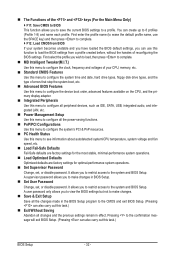
BIOS Setup If this feature. - 33 - This page is dependent on your overall system configurations. Incorrectly doing overclock/overvoltage may result in damage to CPU, chipset, ...
BIOS Setup If this feature. - 33 - This page is dependent on your overall system configurations. Incorrectly doing overclock/overvoltage may result in damage to CPU, chipset, ...
Manual
Page 34
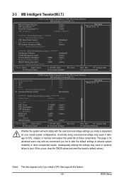
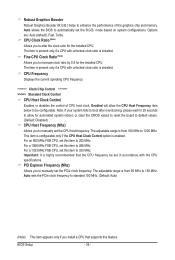
...alter the clock ratio for the installed CPU. For an 800 MHz FSB CPU, set the R.G.B. Important: It is from 90 MHz to 150 MHz. BIOS Setup - 34 - The adjustable range is highly recommended that supports this item to 200 MHz. CPU Frequency Displays the current operating CPU frequency. ******** ... Control CPU Host Clock Control Enables or disables the control of the graphics chip and memory. The adjustable range is installed. Auto allows the BIOS to automatically set this feature. The item is present only if a CPU with unlocked clock ratio is from 100 MHz to 1200 MHz. ...
...alter the clock ratio for the installed CPU. For an 800 MHz FSB CPU, set the R.G.B. Important: It is from 90 MHz to 150 MHz. BIOS Setup - 34 - The adjustable range is highly recommended that supports this item to 200 MHz. CPU Frequency Displays the current operating CPU frequency. ******** ... Control CPU Host Clock Control Enables or disables the control of the graphics chip and memory. The adjustable range is installed. Auto allows the BIOS to automatically set this feature. The item is present only if a CPU with unlocked clock ratio is from 100 MHz to 1200 MHz. ...
Manual
Page 35
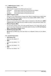
... Host Frequency (Mhz) and System Memory Multiplier settings. the second is the memory frequency that is the normal operating frequency of the memory being used; BIOS Setup Extreme Lets the system operate at its good performance level. tRCD Options are : Auto (default), 1~15. System Memory Multiplier (SPD) Allows you to fix...
... Host Frequency (Mhz) and System Memory Multiplier settings. the second is the memory frequency that is the normal operating frequency of the memory being used; BIOS Setup Extreme Lets the system operate at its good performance level. tRCD Options are : Auto (default), 1~15. System Memory Multiplier (SPD) Allows you to fix...
Manual
Page 36
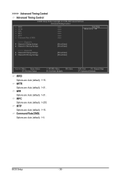
tWR Options are : Auto (default), 1~3. ESC: Exit F1: General Help F7: Optimized Defaults BIOS Setup - 36 - Command Rate(CMD) Options are : Auto (default), 1~31. tWTR Options are : Auto (default), 1~255. tRFC Options are : Auto (default), 1~31. >>>>> Advanced Timing Control ...
tWR Options are : Auto (default), 1~3. ESC: Exit F1: General Help F7: Optimized Defaults BIOS Setup - 36 - Command Rate(CMD) Options are : Auto (default), 1~31. tWTR Options are : Auto (default), 1~255. tRFC Options are : Auto (default), 1~31. >>>>> Advanced Timing Control ...

Manual
Page 37
...: General Help F7: Optimized Defaults - 37 - Trd2wr(Same/Diff Rank) Options are : Auto (default), +800ps~-700ps. tRD Phase1 Adjustment Options are : Auto (default), 0-Normal, 1-Advanced. BIOS Setup tRD Phase3 Adjustment Options are : Auto (default), 0-Normal, 1-Advanced. DIMM2 Clock Skew Control Options are : Auto (default), 1~15. >>>>> Channel A/B Channel A/B Timing Settings CMOS Setup...
...: General Help F7: Optimized Defaults - 37 - Trd2wr(Same/Diff Rank) Options are : Auto (default), +800ps~-700ps. tRD Phase1 Adjustment Options are : Auto (default), 0-Normal, 1-Advanced. BIOS Setup tRD Phase3 Adjustment Options are : Auto (default), 0-Normal, 1-Advanced. DIMM2 Clock Skew Control Options are : Auto (default), 1~15. >>>>> Channel A/B Channel A/B Timing Settings CMOS Setup...
Manual
Page 38
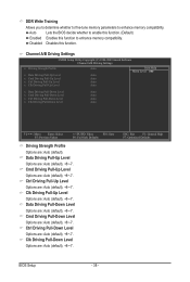
...Pull-Up Level Options are : Auto (default), +8~-7. Cmd Driving Pull-Down Level Options are : Auto (default), +8~-7. ESC: Exit F1: General Help F7: Optimized Defaults BIOS Setup - 38 - Clk Driving Pull-Up Level Options are : Auto (default), +8~-7. DDR Write Training Allows you to determine whether to fine-tune memory parameters to... are : Auto (default). Clk Driving Pull-Down Level Options are: Auto (default), +8~-7. Disabled Disables this function to enhance memory compatibility. Auto Lets the BIOS decide whether to enable this function. (Default) Enabled Enables this function.
...Pull-Up Level Options are : Auto (default), +8~-7. Cmd Driving Pull-Down Level Options are : Auto (default), +8~-7. ESC: Exit F1: General Help F7: Optimized Defaults BIOS Setup - 38 - Clk Driving Pull-Up Level Options are : Auto (default), +8~-7. DDR Write Training Allows you to determine whether to fine-tune memory parameters to... are : Auto (default). Clk Driving Pull-Down Level Options are: Auto (default), +8~-7. Disabled Disables this function to enhance memory compatibility. Auto Lets the BIOS decide whether to enable this function. (Default) Enabled Enables this function.


