
Manual
Page 1
GA-P35T-DQ6 LGA775 socket motherboard for Intel® CoreTM processor family/ Intel® Pentium® processor family/Intel® Celeron® processor family User's Manual Rev. 1003 12ME-P35TDQ6-1003R * The WEEE marking on the product indicates this product must not be disposed of with user's other household waste and must be handed over to a designated collection point for the recycling of waste electrical and electronic equipment!! * The WEEE marking applies only in European Union's member states.
GA-P35T-DQ6 LGA775 socket motherboard for Intel® CoreTM processor family/ Intel® Pentium® processor family/Intel® Celeron® processor family User's Manual Rev. 1003 12ME-P35TDQ6-1003R * The WEEE marking on the product indicates this product must not be disposed of with user's other household waste and must be handed over to a designated collection point for the recycling of waste electrical and electronic equipment!! * The WEEE marking applies only in European Union's member states.

Manual
Page 2
Motherboard GA-P35T-DQ6 Apr. 20, 2007 Motherboard GA-P35T-DQ6 Apr. 20, 2007
Motherboard GA-P35T-DQ6 Apr. 20, 2007 Motherboard GA-P35T-DQ6 Apr. 20, 2007

Manual
Page 4
Table of Contents OptionalItems ...6 Box Contents ...6 GA-P35T-DQ6 Motherboard Layout 7 Block Diagram ...8 Chapter 1 Hardware Installation 9 1-1 Installation Precautions 9 1-2 Product Specifications 10 1-3 Installing the CPU and CPU Cooler 13 1-3-1 Installing the CPU 13 1-3-2 Installing the ...
Table of Contents OptionalItems ...6 Box Contents ...6 GA-P35T-DQ6 Motherboard Layout 7 Block Diagram ...8 Chapter 1 Hardware Installation 9 1-1 Installation Precautions 9 1-2 Product Specifications 10 1-3 Installing the CPU and CPU Cooler 13 1-3-1 Installing the CPU 13 1-3-2 Installing the ...

Manual
Page 6
... 2.0 bracket (Part No. 12CR1-1UB030-21/R) 2-port IEEE 1394a bracket (Part No. 12CF1-1IE008-01/R) S/PDIF in cable (Part No. 12CR1-1SPDIN-01/R) - 6 - Box Contents GA-P35T-DQ6 motherboard Motherboard driver disk User's Manual Quick Installation Guide Intel® LGA775 CPU Installation Guide One IDE cable and one floppy disk drive cable Four...
... 2.0 bracket (Part No. 12CR1-1UB030-21/R) 2-port IEEE 1394a bracket (Part No. 12CF1-1IE008-01/R) S/PDIF in cable (Part No. 12CR1-1SPDIN-01/R) - 6 - Box Contents GA-P35T-DQ6 motherboard Motherboard driver disk User's Manual Quick Installation Guide Intel® LGA775 CPU Installation Guide One IDE cable and one floppy disk drive cable Four...

Manual
Page 7
GA-P35T-DQ6 Motherboard Layout KB_MS COAXIAL OPTICAL SYS_FAN1 ATX_12V_2X LGA775 PWR_FAN PCIE_12V ATX COMA LPT USB 1394 GA-P35T-DQ6 USB LAN F_AUDIO CPU_FAN AUDIO PCIE_1 Intel® P35 FDD RTL8111B PCIE_16_1 NB_FAN DDRIII1 DDRIII2 DDRIII3 DDRIII4 CODEC CD_IN PCIE_2 BP_BIOS MAIN_BIOS PCIE_3 PCIE_16_2 BATTERY CLR_CMOS PCI1 TSB43AB23 IT8718 PCI2 SPDIF_IN TPM CI SYS_FAN2 F_USB4 F_USB3 F_USB2 F_USB1 Intel® ICH9R SATAII4 SATAII5 SATAII0 SATAII1 SATAII2 SATAII3 GIGABYTE SATA2 IDE F1_1394 F2_1394 PWR_LED F_PANEL GSATAII0 GSATAII1 - 7 -
GA-P35T-DQ6 Motherboard Layout KB_MS COAXIAL OPTICAL SYS_FAN1 ATX_12V_2X LGA775 PWR_FAN PCIE_12V ATX COMA LPT USB 1394 GA-P35T-DQ6 USB LAN F_AUDIO CPU_FAN AUDIO PCIE_1 Intel® P35 FDD RTL8111B PCIE_16_1 NB_FAN DDRIII1 DDRIII2 DDRIII3 DDRIII4 CODEC CD_IN PCIE_2 BP_BIOS MAIN_BIOS PCIE_3 PCIE_16_2 BATTERY CLR_CMOS PCI1 TSB43AB23 IT8718 PCI2 SPDIF_IN TPM CI SYS_FAN2 F_USB4 F_USB3 F_USB2 F_USB1 Intel® ICH9R SATAII4 SATAII5 SATAII0 SATAII1 SATAII2 SATAII3 GIGABYTE SATA2 IDE F1_1394 F2_1394 PWR_LED F_PANEL GSATAII0 GSATAII1 - 7 -

Manual
Page 10
...174; 4 processor Extreme Edition/Intel® Pentium® 4 processor/ Intel® Celeron® D processor in the LGA 775 package (Go to GIGABYTE's website for the latest CPU support list.) Š Support for Intel® Hyper-Threading Technology Š L2 cache varies with the PCIE_16_2 slot)... RAID 0, RAID 1, RAID 5, and RAID 10 Š GIGABYTE SATA2 chip: - 1 x IDE connector supporting ATA-133/100/66/33 and up to 2 IDE devices - 2 x SATA 3 Gb/s connectors (GSATAII0, GSATAII1) supporting up to the internal IEEE 1394 headers) GA-P35T-DQ6 Motherboard - 10 - TSB43AB23 chip Š Up to 3...
...174; 4 processor Extreme Edition/Intel® Pentium® 4 processor/ Intel® Celeron® D processor in the LGA 775 package (Go to GIGABYTE's website for the latest CPU support list.) Š Support for Intel® Hyper-Threading Technology Š L2 cache varies with the PCIE_16_2 slot)... RAID 0, RAID 1, RAID 5, and RAID 10 Š GIGABYTE SATA2 chip: - 1 x IDE connector supporting ATA-133/100/66/33 and up to 2 IDE devices - 2 x SATA 3 Gb/s connectors (GSATAII0, GSATAII1) supporting up to the internal IEEE 1394 headers) GA-P35T-DQ6 Motherboard - 10 - TSB43AB23 chip Š Up to 3...

Manual
Page 12
...; Support for Virtual Dual BIOS Š Norton Internet Security (OEM version) Š Voltage adjustments in BIOS Setup (CPU/DDR3/PCIe/FSB/(G)MCH) allow you to: - GA-P35T-DQ6 Motherboard - 12 -
...; Support for Virtual Dual BIOS Š Norton Internet Security (OEM version) Š Voltage adjustments in BIOS Setup (CPU/DDR3/PCIe/FSB/(G)MCH) allow you to: - GA-P35T-DQ6 Motherboard - 12 -

Manual
Page 14
... turn off the computer and unplug the power cord from the power outlet to prevent damage to correctly install the CPU into its locked position. GA-P35T-DQ6 Motherboard - 14 -
... turn off the computer and unplug the power cord from the power outlet to prevent damage to correctly install the CPU into its locked position. GA-P35T-DQ6 Motherboard - 14 -

Manual
Page 16
... shown in appearance from the back of turns. Tools needed: 1. Do not fasten it to your CPU cooler installation manual for the other spring screw. GA-P35T-DQ6 Motherboard - 16 - Step 7: Finally, you may vary in the picture to the left and remove the screws. Step 4: After removing/unfastening the screws, you can...
... shown in appearance from the back of turns. Tools needed: 1. Do not fasten it to your CPU cooler installation manual for the other spring screw. GA-P35T-DQ6 Motherboard - 16 - Step 7: Finally, you may vary in the picture to the left and remove the screws. Step 4: After removing/unfastening the screws, you can...

Manual
Page 18
... the retaining clips at both ends of the memory socket. As indicated in the picture on the left, place your memory modules in one direction. GA-P35T-DQ6 Motherboard - 18 - Notch DDR3 DIMM A DDR3 memory module has a notch, so it vertically into place when the memory module is securely inserted. Step 2: The clips...
... the retaining clips at both ends of the memory socket. As indicated in the picture on the left, place your memory modules in one direction. GA-P35T-DQ6 Motherboard - 18 - Notch DDR3 DIMM A DDR3 memory module has a notch, so it vertically into place when the memory module is securely inserted. Step 2: The clips...

Manual
Page 20
English • Removing the Card from the PCIE_16_2 Slot: Press the white latch at the end of the PCI Express x16 slot to release the card and then pull the card straight up from your power supply to the onboard PCI Express x16 slots. GA-P35T-DQ6 Motherboard - 20 - When you install two graphics cards, connect the power cable from the slot. • The motherboard provides a PCIE_12V power connector, which can supply extra power to this connector.
English • Removing the Card from the PCIE_16_2 Slot: Press the white latch at the end of the PCI Express x16 slot to release the card and then pull the card straight up from your power supply to the onboard PCI Express x16 slots. GA-P35T-DQ6 Motherboard - 20 - When you install two graphics cards, connect the power cable from the slot. • The motherboard provides a PCIE_12V power connector, which can supply extra power to this connector.

Manual
Page 22
.... Serial Port Use the serial port to an external audio system that supports digital coaxial audio. USB Port The USB port supports the USB 2.0/1.1 specification. GA-P35T-DQ6 Motherboard - 22 - IEEE 1394a Port The IEEE 1394 port supports the IEEE 1394a specification, featuring high speed, high bandwidth and hotplug capabilities. RJ-45 LAN...
.... Serial Port Use the serial port to an external audio system that supports digital coaxial audio. USB Port The USB port supports the USB 2.0/1.1 specification. GA-P35T-DQ6 Motherboard - 22 - IEEE 1394a Port The IEEE 1394 port supports the IEEE 1394a specification, featuring high speed, high bandwidth and hotplug capabilities. RJ-45 LAN...

Manual
Page 24
... 17) F_USB1/F_USB2/F_USB3/F_USB4 18) F1_1394/F2_1394 19) TPM 20) CLR_CMOS 21) CI 22) BATTERY Read the following guidelines before turning on the motherboard. GA-P35T-DQ6 Motherboard - 24 - Unplug the power cord from the power outlet to prevent damage to the devices. • After installing the device and before connecting external...
... 17) F_USB1/F_USB2/F_USB3/F_USB4 18) F1_1394/F2_1394 19) TPM 20) CLR_CMOS 21) CI 22) BATTERY Read the following guidelines before turning on the motherboard. GA-P35T-DQ6 Motherboard - 24 - Unplug the power cord from the power outlet to prevent damage to the devices. • After installing the device and before connecting external...
Manual
Page 26
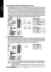
... power connector wires. The motherboard supports CPU fan speed control, which requires the use of a CPU fan with color-coded power connector wires. Pin No. GA-P35T-DQ6 Motherboard - 26 - Definition 1 GND 2 +12V 3 Sense 6) NB_FAN (North Bridge Fan Header) Connect the North Bridge fan cable to the CPU/North Bridge or the system...
... power connector wires. The motherboard supports CPU fan speed control, which requires the use of a CPU fan with color-coded power connector wires. Pin No. GA-P35T-DQ6 Motherboard - 26 - Definition 1 GND 2 +12V 3 Sense 6) NB_FAN (North Bridge Fan Header) Connect the North Bridge fan cable to the CPU/North Bridge or the system...

Manual
Page 28
... and the total number of the IDE devices (for example, master or slave). (For information about configuring master/slave settings for instructions on the connector. GA-P35T-DQ6 Motherboard - 28 - Refer to Chapter 5, "Configuring SATA Hard Drive(s)," for the IDE devices, read the instructions from the device manufacturers.) 1 2 39 40 10) SATAII0/1/2/3/4/5 (SATA...
... and the total number of the IDE devices (for example, master or slave). (For information about configuring master/slave settings for instructions on the connector. GA-P35T-DQ6 Motherboard - 28 - Refer to Chapter 5, "Configuring SATA Hard Drive(s)," for the IDE devices, read the instructions from the device manufacturers.) 1 2 39 40 10) SATAII0/1/2/3/4/5 (SATA...

Manual
Page 30
... to restart the computer if the computer freezes and fails to the speaker on the chassis front panel. PW+ PWSPEAK+ SPEAK- 2 20 1 19 HD+ HD- GA-P35T-DQ6 Motherboard - 30 - The S0 On LED is on when the system is in S1 sleep state. The LED keeps blinking when S1 Blinking the system...
... to restart the computer if the computer freezes and fails to the speaker on the chassis front panel. PW+ PWSPEAK+ SPEAK- 2 20 1 19 HD+ HD- GA-P35T-DQ6 Motherboard - 30 - The S0 On LED is on when the system is in S1 sleep state. The LED keeps blinking when S1 Blinking the system...

Manual
Page 32
... computer and unplug the power cord from the power outlet to prevent damage to USB 2.0/1.1 specification. For purchasing the optional S/PDIF in cable. Pin No. GA-P35T-DQ6 Motherboard - 32 - Each USB header can connect to an audio device that supports digital audio out via an optional USB bracket. English 16) SPDIF_IN (S/PDIF...
... computer and unplug the power cord from the power outlet to prevent damage to USB 2.0/1.1 specification. For purchasing the optional S/PDIF in cable. Pin No. GA-P35T-DQ6 Motherboard - 32 - Each USB header can connect to an audio device that supports digital audio out via an optional USB bracket. English 16) SPDIF_IN (S/PDIF...

Manual
Page 34
Open: Normal Short: Clear CMOS Values • Always turn off your computer and unplug the power cord from the jumper. Pin No. Definition 1 1 Signal 2 GND GA-P35T-DQ6 Motherboard - 34 - Failure to do so may cause damage to the motherboard. • After system restart, go to BIOS Setup to load factory defaults (select ...
Open: Normal Short: Clear CMOS Values • Always turn off your computer and unplug the power cord from the jumper. Pin No. Definition 1 1 Signal 2 GND GA-P35T-DQ6 Motherboard - 34 - Failure to do so may cause damage to the motherboard. • After system restart, go to BIOS Setup to load factory defaults (select ...

Manual
Page 36
English GA-P35T-DQ6 Motherboard - 36 -
English GA-P35T-DQ6 Motherboard - 36 -
Manual
Page 38
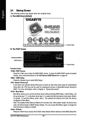
.... To exit Boot Menu, press . After system restart, the device boot order will directly boot from the device configured in Boot Menu is effective for P35T-DQ6 F1d . . . . The LOGO Sceen (Default) : POST Screen : BIOS Setup/Q-Flash : XpressRecovery2 : Boot Menu: Qflash Function Keys B. GA-P35T-DQ6 Motherboard - 38 -
.... To exit Boot Menu, press . After system restart, the device boot order will directly boot from the device configured in Boot Menu is effective for P35T-DQ6 F1d . . . . The LOGO Sceen (Default) : POST Screen : BIOS Setup/Q-Flash : XpressRecovery2 : Boot Menu: Qflash Function Keys B. GA-P35T-DQ6 Motherboard - 38 -
