Manual
Page 1
GA-P35C-DS3R/ GA-P35C-DS3/ GA-P35C-S3 LGA775 socket motherboard for Intel® CoreTM processor family/ Intel® Pentium® processor family/Intel® Celeron® processor family User's Manual Rev. 2002 12ME-P35CDS3R-2002R * The WEEE marking on the product indicates this product must not be disposed of with user's other household waste and must be handed over to a designated collection point for the recycling of waste electrical and electronic equipment!! * The WEEE marking applies only in European Union's member states.
GA-P35C-DS3R/ GA-P35C-DS3/ GA-P35C-S3 LGA775 socket motherboard for Intel® CoreTM processor family/ Intel® Pentium® processor family/Intel® Celeron® processor family User's Manual Rev. 2002 12ME-P35CDS3R-2002R * The WEEE marking on the product indicates this product must not be disposed of with user's other household waste and must be handed over to a designated collection point for the recycling of waste electrical and electronic equipment!! * The WEEE marking applies only in European Union's member states.
Manual
Page 3
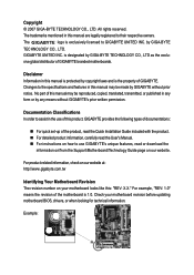
... revision number on our website. by any means without prior notice. Example: All rights reserved. Changes to GIGABYTE UNITED INC. No part of the motherboard is designated by GIGABYTE without GIGABYTE's prior written permission. For example, "REV: 1.0" means the revision of this manual is protected by copyright laws and is exclusively licensed to the...
... revision number on our website. by any means without prior notice. Example: All rights reserved. Changes to GIGABYTE UNITED INC. No part of the motherboard is designated by GIGABYTE without GIGABYTE's prior written permission. For example, "REV: 1.0" means the revision of this manual is protected by copyright laws and is exclusively licensed to the...
Manual
Page 24
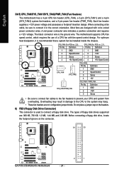
...that a system fan be sure to connect a floppy disk drive. Do not place a jumper cap on the connector. 34 33 GA-P35C-DS3R/DS3/S3 Motherboard - 24 - 2 1 Before connecting a floppy disk drive, locate the foolproof groove on the headers. 6) FDD (...design. When connecting a fan cable, be installed inside the chassis. A red power connector wire indicates a positive connection and requires a +12V voltage. CPU_FAN (For PCB rev. 2.0): Pin No. Definition 1 GND 2 +12V 3 Sense 4 +5V / Speed Control 1 CPU_FAN 1 SYS_FAN2 1 SYS_FAN1/PWR_FAN SYS_FAN2: Pin No. 1 Definition GND ...
...that a system fan be sure to connect a floppy disk drive. Do not place a jumper cap on the connector. 34 33 GA-P35C-DS3R/DS3/S3 Motherboard - 24 - 2 1 Before connecting a floppy disk drive, locate the foolproof groove on the headers. 6) FDD (...design. When connecting a fan cable, be installed inside the chassis. A red power connector wire indicates a positive connection and requires a +12V voltage. CPU_FAN (For PCB rev. 2.0): Pin No. Definition 1 GND 2 +12V 3 Sense 4 +5V / Speed Control 1 CPU_FAN 1 SYS_FAN2 1 SYS_FAN1/PWR_FAN SYS_FAN2: Pin No. 1 Definition GND ...


