Manual
Page 1
GA-P35C-DS3R/ GA-P35C-DS3/ GA-P35C-S3 LGA775 socket motherboard for Intel® CoreTM processor family/ Intel® Pentium® processor family/Intel® Celeron® processor family User's Manual Rev. 2002 12ME-P35CDS3R-2002R * The WEEE marking on the product indicates this product must not be disposed of with user's other household waste and must be handed over to a designated collection point for the recycling of waste electrical and electronic equipment!! * The WEEE marking applies only in European Union's member states.
GA-P35C-DS3R/ GA-P35C-DS3/ GA-P35C-S3 LGA775 socket motherboard for Intel® CoreTM processor family/ Intel® Pentium® processor family/Intel® Celeron® processor family User's Manual Rev. 2002 12ME-P35CDS3R-2002R * The WEEE marking on the product indicates this product must not be disposed of with user's other household waste and must be handed over to a designated collection point for the recycling of waste electrical and electronic equipment!! * The WEEE marking applies only in European Union's member states.
Manual
Page 2
Motherboard GA-P35C-DS3R/GA-P35C-DS3/GA-P35C-S3 Jul. 26, 2007 Motherboard GA-P35C-DS3R/GA-P35C-DS3/ GA-P35C-S3 Jul. 26, 2007
Motherboard GA-P35C-DS3R/GA-P35C-DS3/GA-P35C-S3 Jul. 26, 2007 Motherboard GA-P35C-DS3R/GA-P35C-DS3/ GA-P35C-S3 Jul. 26, 2007

Manual
Page 4
Table of Contents Box Contents ...6 OptionalItems ...6 GA-P35C-DS3R/DS3/S3 Motherboard Layout 7 Block Diagram ...8 Chapter 1 Hardware Installation 9 1-1 Installation Precautions 9 1-2 Product Specifications 10 1-3 Installing the CPU and CPU Cooler 13 1-3-1 Installing the CPU 13 1-3-2 Installing ...
Table of Contents Box Contents ...6 OptionalItems ...6 GA-P35C-DS3R/DS3/S3 Motherboard Layout 7 Block Diagram ...8 Chapter 1 Hardware Installation 9 1-1 Installation Precautions 9 1-2 Product Specifications 10 1-3 Installing the CPU and CPU Cooler 13 1-3-1 Installing the CPU 13 1-3-2 Installing ...
Manual
Page 5
... EasyTune 5 ...73 4-4 Windows Vista ReadyBoost 74 Chapter 5 Appendix ...75 5-1 Configuring SATA Hard Drive(s 75 5-1-1 Configuring Intel ICH9R SATA Controllers 75 5-1-2 Configuring GIGABYTE SATA2 SATA Controller 81 5-1-3 Making a SATA RAID/AHCI Driver Diskette 87 5-1-4 Installing the SATA RAID/AHCI Driver and Operating System 88 5-2 Configuring Audio Input and... Recording 100 5-2-4 Using the Sound Recorder 102 5-3 Troubleshooting 103 5-3-1 Frequently Asked Questions 103 5-3-2 Troubleshooting Procedure 104 Regulatory Statements 107 Only the GA-P35C-DS3R supports RAID function. - 5 -
... EasyTune 5 ...73 4-4 Windows Vista ReadyBoost 74 Chapter 5 Appendix ...75 5-1 Configuring SATA Hard Drive(s 75 5-1-1 Configuring Intel ICH9R SATA Controllers 75 5-1-2 Configuring GIGABYTE SATA2 SATA Controller 81 5-1-3 Making a SATA RAID/AHCI Driver Diskette 87 5-1-4 Installing the SATA RAID/AHCI Driver and Operating System 88 5-2 Configuring Audio Input and... Recording 100 5-2-4 Using the Sound Recorder 102 5-3 Troubleshooting 103 5-3-1 Frequently Asked Questions 103 5-3-2 Troubleshooting Procedure 104 Regulatory Statements 107 Only the GA-P35C-DS3R supports RAID function. - 5 -
Manual
Page 6
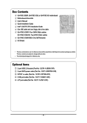
... (Part No. 12CF1-1LP001-01R) - 6 - Box Contents GA-P35C-DS3R, GA-P35C-DS3, or GA-P35C-S3 motherboard Motherboard driver disk User's Manual Quick Installation Guide Intel® LGA775 CPU Installation Guide One IDE cable and one floppy disk drive cable GA-P35C-DS3R: Four SATA 3Gb/s cables GA-P35C-DS3/S3: Two SATA 3Gb/s cables GA-P35C-DS3R/DS3: One SATA bracket I/O Shield • The box contents...
... (Part No. 12CF1-1LP001-01R) - 6 - Box Contents GA-P35C-DS3R, GA-P35C-DS3, or GA-P35C-S3 motherboard Motherboard driver disk User's Manual Quick Installation Guide Intel® LGA775 CPU Installation Guide One IDE cable and one floppy disk drive cable GA-P35C-DS3R: Four SATA 3Gb/s cables GA-P35C-DS3/S3: Two SATA 3Gb/s cables GA-P35C-DS3R/DS3: One SATA bracket I/O Shield • The box contents...

Manual
Page 7
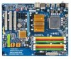
... ATX R_USB1 R_USB2 R_USB3 SYS_FAN2 GA-P35C-DS3R/DS3/S3 USB LAN F_AUDIO AUDIO SYS_FAN1 RTL8111B PCIE_3 PCIE_16 CODEC PCIE_1 PCIE_2 SPDIF_O PCI1 SPDIF_I PCI2 IT8718 PCI3 CD_IN COMA Intel® P35 DDRIII2 DDRII3 DDRII4 DDRIII1 DDRII2 DDRII1 FDD PWR_FAN Intel® ICH9R /ICH9 SATAII2 SATAII3 BAT GSATAII0 CLR_CMOS GSATAII1 GIGABYTE SATA2 / JMicron 368 BIOS...
... ATX R_USB1 R_USB2 R_USB3 SYS_FAN2 GA-P35C-DS3R/DS3/S3 USB LAN F_AUDIO AUDIO SYS_FAN1 RTL8111B PCIE_3 PCIE_16 CODEC PCIE_1 PCIE_2 SPDIF_O PCI1 SPDIF_I PCI2 IT8718 PCI3 CD_IN COMA Intel® P35 DDRIII2 DDRII3 DDRII4 DDRIII1 DDRII2 DDRII1 FDD PWR_FAN Intel® ICH9R /ICH9 SATAII2 SATAII3 BAT GSATAII0 CLR_CMOS GSATAII1 GIGABYTE SATA2 / JMicron 368 BIOS...
Manual
Page 8
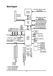
Only for GA-P35C-DS3. Only for GA-P35C-S3. - 8 - Block Diagram PCIe CLK (100 MHz) PCI Express x16 LAN RJ45 PCIe CLK (100 MHz) Realtek 8111B x1 x1 x1 x1 PCI Express Bus 2 SATA 3Gb/s ATA-133/100/66/ 33 IDE Channel GIGABYTE SATA2 / JMicron 368 PCI Bus LGA775 Processor CPU CLK+/- (400 (O.C.)/333/ 266/200... Speaker Out Center/Subwoofer Speaker Out Side Speaker Out MIC Line-Out Line-In SPDIF In SPDIF Out 3 PCI PCI CLK (33 MHz) Only for GA-P35C-DS3R.
Only for GA-P35C-DS3. Only for GA-P35C-S3. - 8 - Block Diagram PCIe CLK (100 MHz) PCI Express x16 LAN RJ45 PCIe CLK (100 MHz) Realtek 8111B x1 x1 x1 x1 PCI Express Bus 2 SATA 3Gb/s ATA-133/100/66/ 33 IDE Channel GIGABYTE SATA2 / JMicron 368 PCI Bus LGA775 Processor CPU CLK+/- (400 (O.C.)/333/ 266/200... Speaker Out Center/Subwoofer Speaker Out Side Speaker Out MIC Line-Out Line-In SPDIF In SPDIF Out 3 PCI PCI CLK (33 MHz) Only for GA-P35C-DS3R.
Manual
Page 10
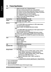
Only for GA-P35C-S3. "*" Only the GA-P35C-DS3R/DS3 adopts All-Solid Capacitor design. Support for SATA RAID 0, RAID 1, RAID 5, and RAID 10 Š iTE IT8718 chip: - 1 x floppy disk drive connector supporting up to 4 SATA 3Gb/s devices (Note 2) - Go to GIGABYTE's website for the latest ...800/667 MHz memory modules (Note: Mixed mode, populating DDR2 and DDR3 memory modules simultaneously is not supported. Only for GA-P35C-DS3. GA-P35C-DS3R/DS3/S3 Motherboard - 10 - English 1-2 Product Specifications CPU Front Side Bus Chipset Memory Audio LAN Expansion Slots Storage Interface &#...
Only for GA-P35C-S3. "*" Only the GA-P35C-DS3R/DS3 adopts All-Solid Capacitor design. Support for SATA RAID 0, RAID 1, RAID 5, and RAID 10 Š iTE IT8718 chip: - 1 x floppy disk drive connector supporting up to 4 SATA 3Gb/s devices (Note 2) - Go to GIGABYTE's website for the latest ...800/667 MHz memory modules (Note: Mixed mode, populating DDR2 and DDR3 memory modules simultaneously is not supported. Only for GA-P35C-DS3. GA-P35C-DS3R/DS3/S3 Motherboard - 10 - English 1-2 Product Specifications CPU Front Side Bus Chipset Memory Audio LAN Expansion Slots Storage Interface &#...
Manual
Page 11
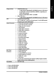
Hardware Installation English Storage Interface Š GIGABYTE SATA2 chip : - 1 x IDE connector supporting ATA-133/100/66/33 and up to 2 IDE devices - 2 x SATA 3Gb/s connectors (GSATAII0, GSATAII1), supporting up to 2 IDE devices ... Š 6 x audio jacks (Center/Subwoofer Speaker Out/Rear Speaker Out/Side Speaker Out/Line In/Line Out/Microphone) I/O Controller Š iTE IT8718 chip Only for GA-P35C-DS3R. Only for GA-P35C-DS3. Only for GA-P35C-S3. - 11 -
Hardware Installation English Storage Interface Š GIGABYTE SATA2 chip : - 1 x IDE connector supporting ATA-133/100/66/33 and up to 2 IDE devices - 2 x SATA 3Gb/s connectors (GSATAII0, GSATAII1), supporting up to 2 IDE devices ... Š 6 x audio jacks (Center/Subwoofer Speaker Out/Rear Speaker Out/Side Speaker Out/Line In/Line Out/Microphone) I/O Controller Š iTE IT8718 chip Only for GA-P35C-DS3R. Only for GA-P35C-DS3. Only for GA-P35C-S3. - 11 -
Manual
Page 12
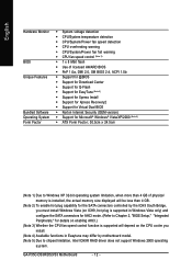
GA-P35C-DS3R/DS3/S3 Motherboard - 12 - English Hardware Monitor BIOS Unique Features Bundled Software Operating System Form Factor Š System voltage detection Š CPU/System temperature detection Š ...
GA-P35C-DS3R/DS3/S3 Motherboard - 12 - English Hardware Monitor BIOS Unique Features Bundled Software Operating System Form Factor Š System voltage detection Š CPU/System temperature detection Š ...
Manual
Page 14
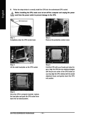
Step 2: Remove the protective socket cover. GA-P35C-DS3R/DS3/S3 Motherboard - 14 - Step 5: Once the CPU is properly inserted, replace the load plate and push the CPU socket lever back into position. Step 4: Hold ...
Step 2: Remove the protective socket cover. GA-P35C-DS3R/DS3/S3 Motherboard - 14 - Step 5: Once the CPU is properly inserted, replace the load plate and push the CPU socket lever back into position. Step 4: Hold ...
Manual
Page 16
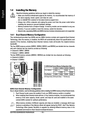
... detect the specifications and capacity of the same capacity, brand, speed, and chips be used . (Go to GIGABYTE's website for optimum performance. After the memory is installed, the BIOS will double the original memory bandwidth. GA-P35C-DS3R/DS3/S3 Motherboard - 16 - English 1-4 Installing the Memory Read the following guidelines before you are installed, a message...
... detect the specifications and capacity of the same capacity, brand, speed, and chips be used . (Go to GIGABYTE's website for optimum performance. After the memory is installed, the BIOS will double the original memory bandwidth. GA-P35C-DS3R/DS3/S3 Motherboard - 16 - English 1-4 Installing the Memory Read the following guidelines before you are installed, a message...
Manual
Page 18
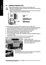
... damage. Locate an expansion slot that came with the slot, and press down on your card. After installing all expansion cards, replace the chassis cover(s). 6. GA-P35C-DS3R/DS3/S3 Motherboard - 18 - PCI Express x1 Slot PCI Express x16 Slot PCI Slot Follow the steps below to make any required BIOS changes for your...
... damage. Locate an expansion slot that came with the slot, and press down on your card. After installing all expansion cards, replace the chassis cover(s). 6. GA-P35C-DS3R/DS3/S3 Motherboard - 18 - PCI Express x1 Slot PCI Express x16 Slot PCI Slot Follow the steps below to make any required BIOS changes for your...

Manual
Page 20
... This connector provides digital audio out to a back panel connector, first remove the cable from your audio system provides an optical digital audio in connector. GA-P35C-DS3R/DS3/S3 Motherboard - 20 - Use this feature, ensure that your device and then remove it from the connector. Connection/ Speed LED Activity LED LAN Port Connection...
... This connector provides digital audio out to a back panel connector, first remove the cable from your audio system provides an optical digital audio in connector. GA-P35C-DS3R/DS3/S3 Motherboard - 20 - Use this feature, ensure that your device and then remove it from the connector. Connection/ Speed LED Activity LED LAN Port Connection...
Manual
Page 22
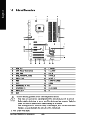
... 16) SPDIF_I 17) F_USB1/F_USB2 18) COMA 19) LPT 20) CLR_CMOS 21) CI Read the following guidelines before turning on the motherboard. GA-P35C-DS3R/DS3/S3 Motherboard - 22 - Only for GA-P35C-DS3R. Unplug the power cord from the power outlet to prevent damage to the devices. • After installing the device and before connecting external...
... 16) SPDIF_I 17) F_USB1/F_USB2 18) COMA 19) LPT 20) CLR_CMOS 21) CI Read the following guidelines before turning on the motherboard. GA-P35C-DS3R/DS3/S3 Motherboard - 22 - Only for GA-P35C-DS3R. Unplug the power cord from the power outlet to prevent damage to the devices. • After installing the device and before connecting external...
Manual
Page 24
... used to prevent your CPU and system from overheating. CPU_FAN (For PCB rev. 2.0): Pin No. Do not place a jumper cap on the connector. 34 33 GA-P35C-DS3R/DS3/S3 Motherboard - 24 - 2 1 English 3/4/5) CPU_FAN/SYS_FAN1/SYS_FAN2/PWR_FAN (Fan Headers) The motherboard has a 4-pin CPU fan header (CPU_FAN), a 3-pin (SYS_FAN1) and a 4-pin (SYS_FAN2) system fan...
... used to prevent your CPU and system from overheating. CPU_FAN (For PCB rev. 2.0): Pin No. Do not place a jumper cap on the connector. 34 33 GA-P35C-DS3R/DS3/S3 Motherboard - 24 - 2 1 English 3/4/5) CPU_FAN/SYS_FAN1/SYS_FAN2/PWR_FAN (Fan Headers) The motherboard has a 4-pin CPU fan header (CPU_FAN), a 3-pin (SYS_FAN1) and a 4-pin (SYS_FAN2) system fan...
Manual
Page 25
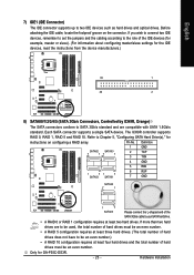
English 7) IDE1 (IDE Connector) The IDE connector supports up to Chapter 5, "Configuring SATA Hard Drive(s)," for GA-P35C-DS3R. - 25 - The ICH9R controller supports RAID 0, RAID 1, RAID 5 and RAID 10. Hardware Installation Definition 1 GND SATAII2 SATAII0 7 17 1 2 TXP 3 TXN 4 GND 5 RXN 1 71 7 SATAII3 SATAII1 6 ...
English 7) IDE1 (IDE Connector) The IDE connector supports up to Chapter 5, "Configuring SATA Hard Drive(s)," for GA-P35C-DS3R. - 25 - The ICH9R controller supports RAID 0, RAID 1, RAID 5 and RAID 10. Hardware Installation Definition 1 GND SATAII2 SATAII0 7 17 1 2 TXP 3 TXN 4 GND 5 RXN 1 71 7 SATAII3 SATAII1 6 ...
Manual
Page 26
English 8) SATAII0/1/4/5 (SATA 3Gb/s Connectors, Controlled by GIGABYTE SATA2, Purple) The SATA connectors conform to SATA 3Gb/s standard and are to be an even number. Only for GA-P35C-DS3R. A RAID 0 or RAID 1 configuration requires at least two hard drives. SATAII0 7 1 1 7 SATAII1 SATAII4 7 1... SATA Hard Drive(s)," for GA-P35C-DS3. Only for GA-P35C-S3. Each SATA connector supports a single SATA device. The GIGABYTE SATA2 controller supports RAID 0 and RAID 1. Only for instructions on configuring a RAID array. GA-P35C-DS3R/DS3/S3 Motherboard - 26 -...
English 8) SATAII0/1/4/5 (SATA 3Gb/s Connectors, Controlled by GIGABYTE SATA2, Purple) The SATA connectors conform to SATA 3Gb/s standard and are to be an even number. Only for GA-P35C-DS3R. A RAID 0 or RAID 1 configuration requires at least two hard drives. SATAII0 7 1 1 7 SATAII1 SATAII4 7 1... SATA Hard Drive(s)," for GA-P35C-DS3. Only for GA-P35C-S3. Each SATA connector supports a single SATA device. The GIGABYTE SATA2 controller supports RAID 0 and RAID 1. Only for instructions on configuring a RAID array. GA-P35C-DS3R/DS3/S3 Motherboard - 26 -...
Manual
Page 28
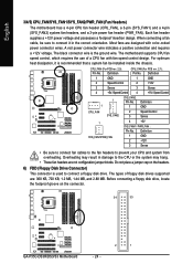
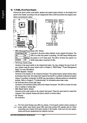
... system is detected at system startup. A front panel module mainly consists of power switch, reset switch, power LED, hard drive activity LED, speaker and etc. GA-P35C-DS3R/DS3/S3 Motherboard - 28 - Message/Power/ Power Sleep LED Switch Speaker Connector MSG+ MSG- One single short beep will be heard if no problem is in...
... system is detected at system startup. A front panel module mainly consists of power switch, reset switch, power LED, hard drive activity LED, speaker and etc. GA-P35C-DS3R/DS3/S3 Motherboard - 28 - Message/Power/ Power Sleep LED Switch Speaker Connector MSG+ MSG- One single short beep will be heard if no problem is in...
Manual
Page 30
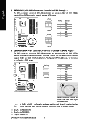
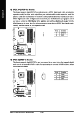
... S/PDIF digital audio cable, carefully read the manual for your motherboard to certain expansion cards like graphics cards and sound cards. Definition 1 Power 2 SPDIFI 3 GND GA-P35C-DS3R/DS3/S3 Motherboard - 30 - For purchasing the optional S/PDIF in cable. Definition 1 1 SPDIFO 2 GND 16) SPDIF_I (S/PDIF In Header) This header supports digital S/PDIF in and...
... S/PDIF digital audio cable, carefully read the manual for your motherboard to certain expansion cards like graphics cards and sound cards. Definition 1 Power 2 SPDIFI 3 GND GA-P35C-DS3R/DS3/S3 Motherboard - 30 - For purchasing the optional S/PDIF in cable. Definition 1 1 SPDIFO 2 GND 16) SPDIF_I (S/PDIF In Header) This header supports digital S/PDIF in and...
