
Manual
Page 3
... information on/from the Support\Motherboard\Technology Guide page on your motherboard revision before updating motherboard BIOS, drivers, or when looking for technical information. For product-related information, check on our website at: http://www.gigabyte.com.tw Identifying Your Motherboard Revision The revision number on our website. Example: by any means...
... information on/from the Support\Motherboard\Technology Guide page on your motherboard revision before updating motherboard BIOS, drivers, or when looking for technical information. For product-related information, check on our website at: http://www.gigabyte.com.tw Identifying Your Motherboard Revision The revision number on our website. Example: by any means...
Manual
Page 4
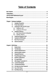
Table of Contents Box Contents ...6 OptionalItems ...6 GA-P35-DS3P Motherboard Layout 7 Block Diagram ...8 Chapter 1 Hardware Installation 9 1-1 Installation Precautions 9 1-2 Product Specifications 10 1-3 Installing the CPU and CPU Cooler 13 ... Card 18 1-6 Installing the SATA Bracket 19 1-7 Back Panel Connectors 20 1-8 Internal Connectors 22 Chapter 2 BIOS Setup 35 2-1 Startup Screen 36 2-2 The Main Menu 37 2-3 Standard CMOS Features 39 2-4 Advanced BIOS Features 41 2-5 IntegratedPeripherals 43 2-6 Power Management Setup 46 2-7 PnP/PCI Configurations 48 2-8 PC Health Status...
Table of Contents Box Contents ...6 OptionalItems ...6 GA-P35-DS3P Motherboard Layout 7 Block Diagram ...8 Chapter 1 Hardware Installation 9 1-1 Installation Precautions 9 1-2 Product Specifications 10 1-3 Installing the CPU and CPU Cooler 13 ... Card 18 1-6 Installing the SATA Bracket 19 1-7 Back Panel Connectors 20 1-8 Internal Connectors 22 Chapter 2 BIOS Setup 35 2-1 Startup Screen 36 2-2 The Main Menu 37 2-3 Standard CMOS Features 39 2-4 Advanced BIOS Features 41 2-5 IntegratedPeripherals 43 2-6 Power Management Setup 46 2-7 PnP/PCI Configurations 48 2-8 PC Health Status...
Manual
Page 5
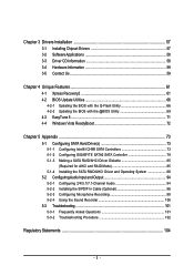
...Information 59 3-5 Contact Us ...59 Chapter 4 Unique Features 61 4-1 Xpress Recovery2 61 4-2 BIOS Update Utilities 66 4-2-1 Updating the BIOS with the Q-Flash Utility 66 4-2-2 Updating the BIOS with the @BIOS Utility 69 4-3 EasyTune 5 ...71 4-4 Windows Vista ReadyBoost 72 Chapter 5 Appendix ...73... 5-1 Configuring SATA Hard Drive(s 73 5-1-1 Configuring Intel® ICH9R SATA Controllers 73 5-1-2 Configuring GIGABYTE SATA2 SATA Controller 79 5-1-3...
...Information 59 3-5 Contact Us ...59 Chapter 4 Unique Features 61 4-1 Xpress Recovery2 61 4-2 BIOS Update Utilities 66 4-2-1 Updating the BIOS with the Q-Flash Utility 66 4-2-2 Updating the BIOS with the @BIOS Utility 69 4-3 EasyTune 5 ...71 4-4 Windows Vista ReadyBoost 72 Chapter 5 Appendix ...73... 5-1 Configuring SATA Hard Drive(s 73 5-1-1 Configuring Intel® ICH9R SATA Controllers 73 5-1-2 Configuring GIGABYTE SATA2 SATA Controller 79 5-1-3...
Manual
Page 8
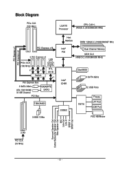
... 2 SATA 3Gb/s ATA-133/100/66/ 33 IDE Channel PCI Bus GIGABYTE SATA2 TSB43AB23 3 IEEE 1394a Host Interface DDR2 1200(O.C.)/1066/800/667 MHz Intel® Dual Channel Memory P35 MCH CLK (400(O.C.)/333/266/200 MHz) Intel® ICH9R CODEC Dual BIOS 6 SATA 3Gb/s 12 USB Ports IT8718 Floppy LPT Port COM...
... 2 SATA 3Gb/s ATA-133/100/66/ 33 IDE Channel PCI Bus GIGABYTE SATA2 TSB43AB23 3 IEEE 1394a Host Interface DDR2 1200(O.C.)/1066/800/667 MHz Intel® Dual Channel Memory P35 MCH CLK (400(O.C.)/333/266/200 MHz) Intel® ICH9R CODEC Dual BIOS 6 SATA 3Gb/s 12 USB Ports IT8718 Floppy LPT Port COM...
Manual
Page 12
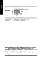
... Center Š Support for Q-Flash Š Support for EasyTune (Note 3) Š Support for Xpress Install Š Support for Xpress Recovery2 Š Support for Virtual Dual BIOS Š Norton Internet Security (OEM version) Š Support for Microsoft® Windows® Vista/XP/2000(Note 4) Š ATX Form Factor; 30.5cm x 24.4cm... 3) Available functions in Easytune may differ by motherboard model. (Note 4) Due to chipset limitation, Intel ICH9R RAID driver does not support Windows 2000 operating system. GA-P35-DS3P Motherboard - 12 -
... Center Š Support for Q-Flash Š Support for EasyTune (Note 3) Š Support for Xpress Install Š Support for Xpress Recovery2 Š Support for Virtual Dual BIOS Š Norton Internet Security (OEM version) Š Support for Microsoft® Windows® Vista/XP/2000(Note 4) Š ATX Form Factor; 30.5cm x 24.4cm... 3) Available functions in Easytune may differ by motherboard model. (Note 4) Due to chipset limitation, Intel ICH9R RAID driver does not support Windows 2000 operating system. GA-P35-DS3P Motherboard - 12 -
Manual
Page 13
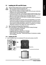
...• A chipset that supports HT Technology • An operating system that the motherboard supports the CPU. (Go to Chapter 2, "BIOS Setup," "Advanced BIOS Features," for the latest CPU support list.) • Always turn on enabling the HT Technology.) 1-3-1 Installing the CPU A. The CPU ...cannot be set the frequency beyond hardware specifications since it enabled (Refer to GIGABYTE's website for instructions on the computer if ...
...• A chipset that supports HT Technology • An operating system that the motherboard supports the CPU. (Go to Chapter 2, "BIOS Setup," "Advanced BIOS Features," for the latest CPU support list.) • Always turn on enabling the HT Technology.) 1-3-1 Installing the CPU A. The CPU ...cannot be set the frequency beyond hardware specifications since it enabled (Refer to GIGABYTE's website for instructions on the computer if ...
Manual
Page 16
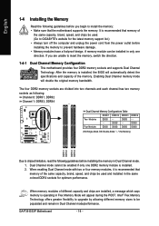
After the memory is installed, the BIOS will double the original memory bandwidth. DS/SS - - Intel® Flex Memory Technology offers greater flexibility to upgrade by allowing different memory sizes to be used . (Go to GIGABYTE's website for optimum performance. GA-P35-DS3P Motherboard - 16 - If you begin to chipset limitation, read the following guidelines before...
After the memory is installed, the BIOS will double the original memory bandwidth. DS/SS - - Intel® Flex Memory Technology offers greater flexibility to upgrade by allowing different memory sizes to be used . (Go to GIGABYTE's website for optimum performance. GA-P35-DS3P Motherboard - 16 - If you begin to chipset limitation, read the following guidelines before...
Manual
Page 18
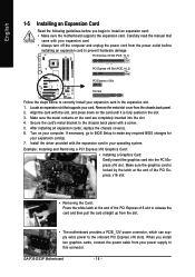
... Express x16 slot to release the card and then pull the card straight up from the chassis back panel. 2. If necessary, go to BIOS Setup to this connector. Example: Installing and Removing a PCI Express x16 Graphics Card: • Installing a Graphics Card: Gently insert the ...from the power outlet before you install two graphics cards, connect the power cable from your power supply to make any required BIOS changes for your expansion card(s). 7. GA-P35-DS3P Motherboard - 18 - Carefully read the manual that supports your computer. PCI Express x16 Slot (PCIE_16_1) PCI Express x16 ...
... Express x16 slot to release the card and then pull the card straight up from the chassis back panel. 2. If necessary, go to BIOS Setup to this connector. Example: Installing and Removing a PCI Express x16 Graphics Card: • Installing a Graphics Card: Gently insert the ...from the power outlet before you install two graphics cards, connect the power cable from your power supply to make any required BIOS changes for your expansion card(s). 7. GA-P35-DS3P Motherboard - 18 - Carefully read the manual that supports your computer. PCI Express x16 Slot (PCIE_16_1) PCI Express x16 ...
Manual
Page 28
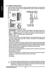
...BIOS Setup," "Power Management Setup," for information about beep codes. • HD (IDE Hard Drive Activity LED, Blue) Connects to the power status indicator on the chassis front panel. Message/Power/ Power Sleep LED Switch Speaker Connector MSG+ MSG- The LED is on the chassis front panel. GA-P35-DS3P...front panel. The S0 On LED is on the chassis front panel. The LED keeps blinking when S1 Blinking the system is detected, the BIOS may differ by issuing a beep code. Refer to Chapter 5, "Troubleshooting," for more information). • SPEAK (Speaker, Orange): Connects to...
...BIOS Setup," "Power Management Setup," for information about beep codes. • HD (IDE Hard Drive Activity LED, Blue) Connects to the power status indicator on the chassis front panel. Message/Power/ Power Sleep LED Switch Speaker Connector MSG+ MSG- The LED is on the chassis front panel. GA-P35-DS3P...front panel. The S0 On LED is on the chassis front panel. The LED keeps blinking when S1 Blinking the system is detected, the BIOS may differ by issuing a beep code. Refer to Chapter 5, "Troubleshooting," for more information). • SPEAK (Speaker, Orange): Connects to...
Manual
Page 33
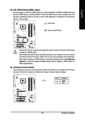
... the two pins to temporarily short the two pins or use a metal object like a screwdriver to touch the two pins for BIOS configurations). 23) CI (Chassis Intrusion Header) This motherboard provides a chassis detection feature that detects if the chassis cover has been ... 22) CLR_CMOS (Clearing CMOS Jumper) Use this jumper to factory defaults. This function requires a chassis with chassis intrusion detection design. date information and BIOS configurations) and reset the CMOS values to clear the CMOS values (e.g. Definition 1 1 Signal 2 GND - 33 - Open: Normal Short: Clear ...
... the two pins to temporarily short the two pins or use a metal object like a screwdriver to touch the two pins for BIOS configurations). 23) CI (Chassis Intrusion Header) This motherboard provides a chassis detection feature that detects if the chassis cover has been ... 22) CLR_CMOS (Clearing CMOS Jumper) Use this jumper to factory defaults. This function requires a chassis with chassis intrusion detection design. date information and BIOS configurations) and reset the CMOS values to clear the CMOS values (e.g. Definition 1 1 Signal 2 GND - 33 - Open: Normal Short: Clear ...
Manual
Page 34
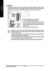
...terminals of the battery holder, making them short for one . English 24) BATTERY The battery provides power to keep the values (such as BIOS configurations, date, and time information) in the CMOS when the computer is replaced with an incorrect model. • Contact the place of... your computer and unplug the power cord before replacing the battery. • Replace the battery with local environmental regulations. Replace the battery. 4. GA-P35-DS3P Motherboard - 34 - You may be accurate or may clear the CMOS values by yourself or uncertain about the battery model. • When ...
...terminals of the battery holder, making them short for one . English 24) BATTERY The battery provides power to keep the values (such as BIOS configurations, date, and time information) in the CMOS when the computer is replaced with an incorrect model. • Contact the place of... your computer and unplug the power cord before replacing the battery. • Replace the battery with local environmental regulations. Replace the battery. 4. GA-P35-DS3P Motherboard - 34 - You may be accurate or may clear the CMOS values by yourself or uncertain about the battery model. • When ...
Manual
Page 35
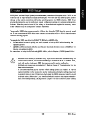
...the battery/clearing CMOS jumper in system malfunction. • BIOS will emit a beep code during the POST when the power is turned off, the battery on the motherboard. To upgrade the BIOS, use either the GIGABYTE Q-Flash or @BIOS utility. • Q-Flash allows the user to clear ...the CMOS values.) - 35 - To see more advanced BIOS Setup menu options, you not flash the BIOS. Inadequately altering the settings may result in Chapter...
...the battery/clearing CMOS jumper in system malfunction. • BIOS will emit a beep code during the POST when the power is turned off, the battery on the motherboard. To upgrade the BIOS, use either the GIGABYTE Q-Flash or @BIOS utility. • Q-Flash allows the user to clear ...the CMOS values.) - 35 - To see more advanced BIOS Setup menu options, you not flash the BIOS. Inadequately altering the settings may result in Chapter...
Manual
Page 36
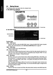
... first boot device setting as needed. : Q-Flash Press the key to accept. The LOGO Screen (Default) :POST Screen :BIOS Setup/Q-Flash :XpressRecovery2 :Boot Menu :Qflash Function Keys B. Note: The setting in Boot Menu. GA-P35-DS3P Motherboard - 36 - After system restart, the device boot order will directly boot from the device configured in Boot...
... first boot device setting as needed. : Q-Flash Press the key to accept. The LOGO Screen (Default) :POST Screen :BIOS Setup/Q-Flash :XpressRecovery2 :Boot Menu :Qflash Function Keys B. Note: The setting in Boot Menu. GA-P35-DS3P Motherboard - 36 - After system restart, the device boot order will directly boot from the device configured in Boot...
Manual
Page 37
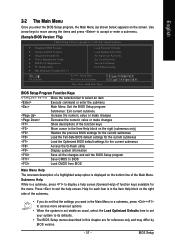
... settings for the current submenus Access the Q-Flash utility Display system information Save all the changes and exit the BIOS Setup program Save CMOS to BIOS Load CMOS from BIOS Main Menu Help The onscreen description of a highlighted setup option is displayed on the screen. English 2-2 The Main Menu Once ...Set User Password Save & Exit Setup Exit Without Saving F8: Q-Flash KLJI: Select Item F10: Save & Exit Setup Time, Date, Hard Disk Type... BIOS Setup Use arrow keys to move among the items and press to exit the help screen (General Help) of the Main Menu.
... settings for the current submenus Access the Q-Flash utility Display system information Save all the changes and exit the BIOS Setup program Save CMOS to BIOS Load CMOS from BIOS Main Menu Help The onscreen description of a highlighted setup option is displayed on the screen. English 2-2 The Main Menu Once ...Set User Password Save & Exit Setup Exit Without Saving F8: Q-Flash KLJI: Select Item F10: Save & Exit Setup Time, Date, Hard Disk Type... BIOS Setup Use arrow keys to move among the items and press to exit the help screen (General Help) of the Main Menu.
Manual
Page 38
...time and date, hard drive types, floppy disk drive types, and the type of errors that stop the system boot, etc. „ Advanced BIOS Features Use this menu to configure the device boot order, advanced features available on the CPU, and the primary display adapter. „ Integrated ... key) and then press to 8 profiles (Profile 1-8) and name each profile. Pressing to the system and BIOS Setup. First enter the profile name (to erase the default profile name, use this task.) GA-P35-DS3P Motherboard - 38 - You can also carry out this function to make changes. „ Save & Exit ...
...time and date, hard drive types, floppy disk drive types, and the type of errors that stop the system boot, etc. „ Advanced BIOS Features Use this menu to configure the device boot order, advanced features available on the CPU, and the primary display adapter. „ Integrated ... key) and then press to 8 profiles (Profile 1-8) and name each profile. Pressing to the system and BIOS Setup. First enter the profile name (to erase the default profile name, use this task.) GA-P35-DS3P Motherboard - 38 - You can also carry out this function to make changes. „ Save & Exit ...

Manual
Page 39
...Values +/-/PU/PD: Value F10: Save F6: Fail-Safe Default ESC: Exit F1: General Help F7: Optimized Defaults Date Sets the system date. BIOS Setup Select the desired field and use the up arrow or down arrow key to CHS. Options are used, set this item to None so... device during the POST for faster system startup. • Manual Allows you to manually enter the specifications of the two methods below : • Auto Lets BIOS automatically detect IDE/SATA devices during the POST. (Default) • None If no IDE/SATA devices are : Auto (default), CHS, LBA, Large. For example, ...
...Values +/-/PU/PD: Value F10: Save F6: Fail-Safe Default ESC: Exit F1: General Help F7: Optimized Defaults Date Sets the system date. BIOS Setup Select the desired field and use the up arrow or down arrow key to CHS. Options are used, set this item to None so... device during the POST for faster system startup. • Manual Allows you to manually enter the specifications of the two methods below : • Auto Lets BIOS automatically detect IDE/SATA devices during the POST. (Default) • None If no IDE/SATA devices are : Auto (default), CHS, LBA, Large. For example, ...
Manual
Page 40
...heads. All Errors Whenever the BIOS detects a non-fatal error the system boot will stop for all other errors. Base Memory Also called conventional memory. Typically, 640 KB will not stop for a keyboard or a floppy disk drive error but stop for any error. GA-P35-DS3P Motherboard - 40 - The ...of the device during the POST for an error during the POST. (Default) • None If no IDE/SATA devices are determined by the BIOS POST. Total Memory The total amount of extended memory. Options are : Disabled (default), Drive A. Floppy 3 Mode Support Allows you wish to ...
...heads. All Errors Whenever the BIOS detects a non-fatal error the system boot will stop for all other errors. Base Memory Also called conventional memory. Typically, 640 KB will not stop for a keyboard or a floppy disk drive error but stop for any error. GA-P35-DS3P Motherboard - 40 - The ...of the device during the POST for an error during the POST. (Default) • None If no IDE/SATA devices are determined by the BIOS POST. Total Memory The total amount of extended memory. Options are : Disabled (default), Drive A. Floppy 3 Mode Support Allows you wish to ...
Manual
Page 41
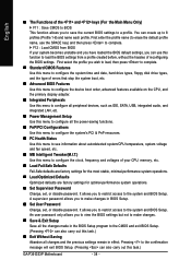
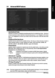
...- First/Second/Third Boot Device Specifies the boot order from the installed hard drives. BIOS Setup This feature allows your hard drive. This feature only works for entering the BIOS Setup program. Password Check Specifies whether a password is required every time the system boots... System A password is only required for entering the BIOS Setup program. (Default) A password is present only if you enter BIOS Setup. English 2-4 Advanced BIOS Features CMOS Setup Utility-Copyright (C) 1984-2007 Award Software Advanced BIOS Features ` Hard Disk Boot Priority First Boot Device Second...
...- First/Second/Third Boot Device Specifies the boot order from the installed hard drives. BIOS Setup This feature allows your hard drive. This feature only works for entering the BIOS Setup program. Password Check Specifies whether a password is required every time the system boots... System A password is only required for entering the BIOS Setup program. (Default) A password is present only if you enter BIOS Setup. English 2-4 Advanced BIOS Features CMOS Setup Utility-Copyright (C) 1984-2007 Award Software Advanced BIOS Features ` Hard Disk Boot Priority First Boot Device Second...
Manual
Page 43
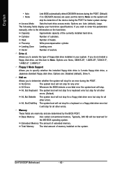
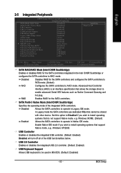
... wish to AHCI mode. USB Controller Enables or disables the integrated USB controller. (Default: Enabled) Disabled will turn off all of the integrated SATA controllers. BIOS Setup English 2-5 Integrated Peripherals CMOS Setup Utility-Copyright (C) 1984-2007 Award Software Integrated Peripherals SATA RAID/AHCI Mode SATA Port0-3 Native Mode USB Controller USB...
... wish to AHCI mode. USB Controller Enables or disables the integrated USB controller. (Default: Enabled) Disabled will turn off all of the integrated SATA controllers. BIOS Setup English 2-5 Integrated Peripherals CMOS Setup Utility-Copyright (C) 1984-2007 Award Software Integrated Peripherals SATA RAID/AHCI Mode SATA Port0-3 Native Mode USB Controller USB...
Manual
Page 45
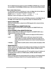
...2E8/IRQ3, Disabled. Onboard Parallel Port Enables or disables the onboard parallel port (LPT) and specifies its base I /O address and corresponding interrupt. BIOS Setup If a cable problem occurs on Pair 1-2. Parallel Port Mode Selects an operating mode for the SATA controller and configures the SATA controller to ... at a normal speed of 10/100/1000Mbps in Windows mode or when the LAN Boot ROM is activated. Options are not used in the GIGABYTE SATA 2 chip or configures the SATA controller to AHCI mode. Options are : 378/IRQ7 (default), 278/IRQ5, 3BC/IRQ7, Disabled. IDE...
...2E8/IRQ3, Disabled. Onboard Parallel Port Enables or disables the onboard parallel port (LPT) and specifies its base I /O address and corresponding interrupt. BIOS Setup If a cable problem occurs on Pair 1-2. Parallel Port Mode Selects an operating mode for the SATA controller and configures the SATA controller to ... at a normal speed of 10/100/1000Mbps in Windows mode or when the LAN Boot ROM is activated. Options are not used in the GIGABYTE SATA 2 chip or configures the SATA controller to AHCI mode. Options are : 378/IRQ7 (default), 278/IRQ5, 3BC/IRQ7, Disabled. IDE...


