Manual
Page 4
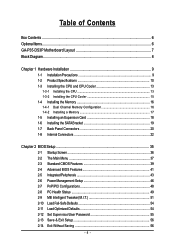
Table of Contents Box Contents ...6 OptionalItems ...6 GA-P35-DS3P Motherboard Layout 7 Block Diagram ...8 Chapter 1 Hardware Installation 9 1-1 Installation Precautions 9 1-2 Product Specifications 10 1-3 Installing the CPU and CPU Cooler 13 1-3-1 Installing the CPU 13 1-3-2 Installing the CPU Cooler 15 1-4 Installing the Memory 16 1-4-1 Dual Channel Memory Configuration 16 1-4-2 Installing a Memory 17 1-5 Installing an Expansion Card 18 1-6 Installing the SATA Bracket...
Table of Contents Box Contents ...6 OptionalItems ...6 GA-P35-DS3P Motherboard Layout 7 Block Diagram ...8 Chapter 1 Hardware Installation 9 1-1 Installation Precautions 9 1-2 Product Specifications 10 1-3 Installing the CPU and CPU Cooler 13 1-3-1 Installing the CPU 13 1-3-2 Installing the CPU Cooler 15 1-4 Installing the Memory 16 1-4-1 Dual Channel Memory Configuration 16 1-4-2 Installing a Memory 17 1-5 Installing an Expansion Card 18 1-6 Installing the SATA Bracket...
Manual
Page 6
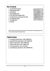
... box contents are for reference only and the actual items shall depend on product package you obtain. Box Contents GA-P35-DS3P motherboard Motherboard Driver Disk User's Manual Quick Installation Guide Intel® LGA775 CPU Installation Guide One IDE cable and one floppy disk drive cable Four SATA 3Gb/s cables One SATA bracket I/O Shield...
... box contents are for reference only and the actual items shall depend on product package you obtain. Box Contents GA-P35-DS3P motherboard Motherboard Driver Disk User's Manual Quick Installation Guide Intel® LGA775 CPU Installation Guide One IDE cable and one floppy disk drive cable Four SATA 3Gb/s cables One SATA bracket I/O Shield...
Manual
Page 8
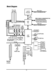
... PCIe CLK (100 MHz) LGA775 Processor CPU CLK+/(400(O.C.)/333/266/200 MHz) PCI Express x16 3 PCI Express x1 LAN PCIe CLK (100 MHz) x1 x1 x1 RJ45 RTL 8111B Switch x1 PCI Express Bus 2 SATA 3Gb/s ATA-133/100/66/ 33 IDE Channel PCI Bus GIGABYTE SATA2 TSB43AB23 3 IEEE 1394a Host... Interface DDR2 1200(O.C.)/1066/800/667 MHz Intel® Dual Channel Memory P35 MCH CLK (400(O.C.)/333/266/200 MHz) Intel® ICH9R CODEC Dual BIOS 6 SATA 3Gb/s 12...
... PCIe CLK (100 MHz) LGA775 Processor CPU CLK+/(400(O.C.)/333/266/200 MHz) PCI Express x16 3 PCI Express x1 LAN PCIe CLK (100 MHz) x1 x1 x1 RJ45 RTL 8111B Switch x1 PCI Express Bus 2 SATA 3Gb/s ATA-133/100/66/ 33 IDE Channel PCI Bus GIGABYTE SATA2 TSB43AB23 3 IEEE 1394a Host... Interface DDR2 1200(O.C.)/1066/800/667 MHz Intel® Dual Channel Memory P35 MCH CLK (400(O.C.)/333/266/200 MHz) Intel® ICH9R CODEC Dual BIOS 6 SATA 3Gb/s 12...

Manual
Page 9
... other hardware components. • When connecting hardware components to the internal connectors on the computer power during the installation process can become damaged as a motherboard, CPU or memory. English Chapter 1 Hardware Installation 1-1 Installation Precautions The motherboard contains numerous delicate electronic circuits and components which can lead to damage to system components...
... other hardware components. • When connecting hardware components to the internal connectors on the computer power during the installation process can become damaged as a motherboard, CPU or memory. English Chapter 1 Hardware Installation 1-1 Installation Precautions The motherboard contains numerous delicate electronic circuits and components which can lead to damage to system components...
Manual
Page 10
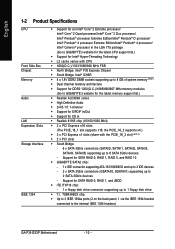
...ports (2 on the back panel, 1 via the IEEE 1394 bracket connected to 1 floppy disk drive Š T.I. English 1-2 Product Specifications CPU Front Side Bus Chipset Memory Audio LAN Expansion Slots Storage Interface IEEE 1394 Š Support for an Intel® CoreTM 2 Extreme processor/...3Gb/s devices - Support for SATA RAID 0, RAID 1, RAID 5, and RAID 10 Š GIGABYTE SATA2 chip: - 1 x IDE connector supporting ATA-133/100/66/33 and up to 2 IDE devices - 2 x SATA 3Gb/s connectors (GSATAII0, GSATAII1) supporting up to the internal IEEE 1394 headers) GA-P35-DS3P Motherboard - 10 -
...ports (2 on the back panel, 1 via the IEEE 1394 bracket connected to 1 floppy disk drive Š T.I. English 1-2 Product Specifications CPU Front Side Bus Chipset Memory Audio LAN Expansion Slots Storage Interface IEEE 1394 Š Support for an Intel® CoreTM 2 Extreme processor/...3Gb/s devices - Support for SATA RAID 0, RAID 1, RAID 5, and RAID 10 Š GIGABYTE SATA2 chip: - 1 x IDE connector supporting ATA-133/100/66/33 and up to 2 IDE devices - 2 x SATA 3Gb/s connectors (GSATAII0, GSATAII1) supporting up to the internal IEEE 1394 headers) GA-P35-DS3P Motherboard - 10 -

Manual
Page 11
...power connector Š 1 x 4-pin PCIe 12V power connector Š 1 x floppy disk drive connector Š 1 x IDE connector Š 8 x SATA 3Gb/s connectors Š 1 x CPU fan header Š 2 x system fan headers Š 1 x power fan header Š 1 x north bridge fan header Š 1 x front panel header Š 1 x front .../Microphone) I/O Controller Š iTE IT8718 chip Hardware Monitor Š System voltage detection Š CPU/System temperature detection Š CPU/System/Power fan speed detection Š CPU overheating warning Š CPU/System/Power fan fail warning Š...
...power connector Š 1 x 4-pin PCIe 12V power connector Š 1 x floppy disk drive connector Š 1 x IDE connector Š 8 x SATA 3Gb/s connectors Š 1 x CPU fan header Š 2 x system fan headers Š 1 x power fan header Š 1 x north bridge fan header Š 1 x front panel header Š 1 x front .../Microphone) I/O Controller Š iTE IT8718 chip Hardware Monitor Š System voltage detection Š CPU/System temperature detection Š CPU/System/Power fan speed detection Š CPU overheating warning Š CPU/System/Power fan fail warning Š...
Manual
Page 13
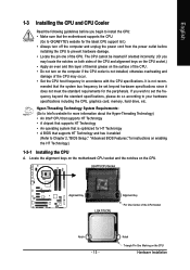
...supports the CPU. (Go to GIGABYTE's website for the peripherals. LGA775 CPU Socket Alignment Key LGA 775 CPU Alignment Key Pin One Corner of the CPU Socket Notch - 13 - Hyper-Threading Technology System Requirements: (Go to Intel's website for more information about the Hyper-Threading Technology) • An Intel® CPU that ...; Do not turn off the computer and unplug the power cord from the power outlet before you begin to install the CPU: • Make sure that the system bus frequency be inserted if oriented incorrectly. (Or you wish to set beyond the standard ...
...supports the CPU. (Go to GIGABYTE's website for the peripherals. LGA775 CPU Socket Alignment Key LGA 775 CPU Alignment Key Pin One Corner of the CPU Socket Notch - 13 - Hyper-Threading Technology System Requirements: (Go to Intel's website for more information about the Hyper-Threading Technology) • An Intel® CPU that ...; Do not turn off the computer and unplug the power cord from the power outlet before you begin to install the CPU: • Make sure that the system bus frequency be inserted if oriented incorrectly. (Or you wish to set beyond the standard ...
Manual
Page 14
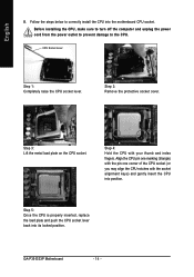
... properly inserted, replace the load plate and push the CPU socket lever back into position. GA-P35-DS3P Motherboard - 14 - Follow the steps below to the CPU. Align the CPU pin one marking (triangle) with the pin one corner of the CPU socket (or you may align the CPU notches with your thumb and index fingers. Step 2: Remove...
... properly inserted, replace the load plate and push the CPU socket lever back into position. GA-P35-DS3P Motherboard - 14 - Follow the steps below to the CPU. Align the CPU pin one marking (triangle) with the pin one corner of the CPU socket (or you may align the CPU notches with your thumb and index fingers. Step 2: Remove...
Manual
Page 15
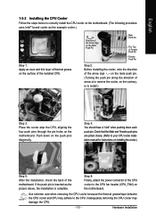
...push pins through the pin holes on the motherboard. Step 6: Finally, attach the power connector of the CPU cooler to the CPU fan header (CPU_FAN) on the surface of the installed CPU. Direction of the Arrow Sign on the Male Push Pin Male Push Pin The Top of Female Push ....) Step 5: After the installation, check the back of arrow is to the CPU. Use extreme care when removing the CPU cooler because the thermal grease/tape between the CPU cooler and CPU may damage the CPU. - 15 - Inadequately removing the CPU cooler may adhere to remove the cooler, on the contrary, is complete.
...push pins through the pin holes on the motherboard. Step 6: Finally, attach the power connector of the CPU cooler to the CPU fan header (CPU_FAN) on the surface of the installed CPU. Direction of the Arrow Sign on the Male Push Pin Male Push Pin The Top of Female Push ....) Step 5: After the installation, check the back of arrow is to the CPU. Use extreme care when removing the CPU cooler because the thermal grease/tape between the CPU cooler and CPU may damage the CPU. - 15 - Inadequately removing the CPU cooler may adhere to remove the cooler, on the contrary, is complete.
Manual
Page 23
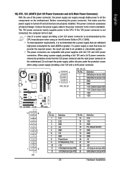
Connect the power supply cable to the CPU. If the 12V power connector is not connected, the computer will not start. • Use of the power connector, the power supply can supply enough .... 3.3V 13 3.3V 14 GND 15 +5V 16 GND 17 +5V 18 GND 19 Power Good 20 5V SB(stand by the CPU manufacturer when using an Intel Extreme Edition CPU (130W). • To meet expansion requirements, it is recommended that a power supply that does not provide the required power, the result...
Connect the power supply cable to the CPU. If the 12V power connector is not connected, the computer will not start. • Use of the power connector, the power supply can supply enough .... 3.3V 13 3.3V 14 GND 15 +5V 16 GND 17 +5V 18 GND 19 Power Good 20 5V SB(stand by the CPU manufacturer when using an Intel Extreme Edition CPU (130W). • To meet expansion requirements, it is recommended that a power supply that does not provide the required power, the result...
Manual
Page 24
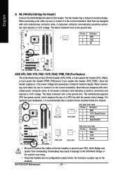
... a +12V voltage. When connecting a fan cable, be installed inside the chassis. 1 CPU_FAN 1 SYS_FAN2 CPU_FAN / SYS_FAN2 : Pin No. GA-P35-DS3P Motherboard - 24 - Each fan header supplies a +12V power voltage and possesses a foolproof insertion design. Most fans are designed with fan speed...power connector wires. Definition 1 1 GND 2 +12V 3 NC 4/5/6) CPU_FAN / SYS_FAN1 / SYS_FAN2 / PWR_FAN (Fan Headers) The motherboard has a 4-pin CPU fan header (CPU_FAN), a 4-pin system fan header (SYS_FAN2), a 3-pin power fan header (PWR_FAN),and a 3-pin system fan header (SYS_FAN1). The ...
... a +12V voltage. When connecting a fan cable, be installed inside the chassis. 1 CPU_FAN 1 SYS_FAN2 CPU_FAN / SYS_FAN2 : Pin No. GA-P35-DS3P Motherboard - 24 - Each fan header supplies a +12V power voltage and possesses a foolproof insertion design. Most fans are designed with fan speed...power connector wires. Definition 1 1 GND 2 +12V 3 NC 4/5/6) CPU_FAN / SYS_FAN1 / SYS_FAN2 / PWR_FAN (Fan Headers) The motherboard has a 4-pin CPU fan header (CPU_FAN), a 4-pin system fan header (SYS_FAN2), a 3-pin power fan header (PWR_FAN),and a 3-pin system fan header (SYS_FAN1). The ...
Manual
Page 38
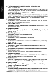
A supervisor password allows you to the confirmation message will exit BIOS Setup. (Pressing can also carry out this task.) GA-P35-DS3P Motherboard - 38 - Pressing to make changes. „ Save & Exit Setup Save all the changes made in the BIOS Setup program to the system ...errors that stop the system boot, etc. „ Advanced BIOS Features Use this menu to configure the device boot order, advanced features available on the CPU, and the primary display adapter. „ Integrated Peripherals Use this menu to configure all peripheral devices, such as IDE, SATA, USB, integrated audio,...
A supervisor password allows you to the confirmation message will exit BIOS Setup. (Pressing can also carry out this task.) GA-P35-DS3P Motherboard - 38 - Pressing to make changes. „ Save & Exit Setup Save all the changes made in the BIOS Setup program to the system ...errors that stop the system boot, etc. „ Advanced BIOS Features Use this menu to configure the device boot order, advanced features available on the CPU, and the primary display adapter. „ Integrated Peripherals Use this menu to configure all peripheral devices, such as IDE, SATA, USB, integrated audio,...
Manual
Page 41
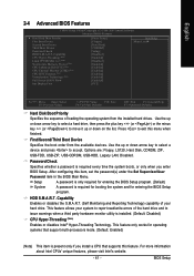
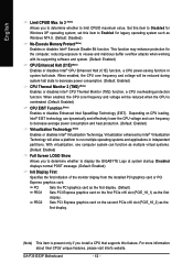
... Advanced BIOS Features ` Hard Disk Boot Priority First Boot Device Second Boot Device Third Boot Device Password Check HDD S.M.A.R.T. Capability CPU Hyper-Threading (Note) Limit CPUID Max. First/Second/Third Boot Device Specifies the boot order from the installed hard drives. ...FDD, USB-ZIP, USB-CDROM, USB-HDD, Legacy LAN, Disabled. to 3 (Note) No-Execute Memory Protect (Note) CPU Enhanced Halt (C1E) (Note) CPU Thermal Monitor 2(TM2) (Note) CPU EIST Function (Note) Virtualization Technology (Note) Full Screen LOGO Show Init Display First [Press Enter] [Floppy] [Hard Disk...
... Advanced BIOS Features ` Hard Disk Boot Priority First Boot Device Second Boot Device Third Boot Device Password Check HDD S.M.A.R.T. Capability CPU Hyper-Threading (Note) Limit CPUID Max. First/Second/Third Boot Device Specifies the boot order from the installed hard drives. ...FDD, USB-ZIP, USB-CDROM, USB-HDD, Legacy LAN, Disabled. to 3 (Note) No-Execute Memory Protect (Note) CPU Enhanced Halt (C1E) (Note) CPU Thermal Monitor 2(TM2) (Note) CPU EIST Function (Note) Virtualization Technology (Note) Full Screen LOGO Show Init Display First [Press Enter] [Floppy] [Hard Disk...
Manual
Page 42
...174; Virtualization Technology will allow a platform to display the GIGABYTE Logo at system startup. With virtualization, one computer system can dynamically and effectively lower the CPU voltage and core frequency to Disabled for legacy operating system ...CPU is present only if you to determine whether to run multiple operating systems and applications in system halt state. Disabled displays normal POST message. (Default: Enabled) Init Display First Specifies the first initiation of the monitor display from the installed PCI graphics card or PCI Express graphics card. GA-P35-DS3P...
...174; Virtualization Technology will allow a platform to display the GIGABYTE Logo at system startup. With virtualization, one computer system can dynamically and effectively lower the CPU voltage and core frequency to Disabled for legacy operating system ...CPU is present only if you to determine whether to run multiple operating systems and applications in system halt state. Disabled displays normal POST message. (Default: Enabled) Init Display First Specifies the first initiation of the monitor display from the installed PCI graphics card or PCI Express graphics card. GA-P35-DS3P...
Manual
Page 49
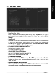
... of the chassis intrusion detection device attached to the motherboard CI header. Current System/CPU Temperature Displays current system/CPU temperature. Current CPU/SYSTEM/Power FAN Speed (RPM) Displays current CPU/system/power fan speed. BIOS Setup Enabled clears the record of previous chassis intrusion ... Case Opened Vcore DDR18V +3.3V +12V Current System Temperature Current CPU Temperature Current CPU FAN Speed Current SYSTEM FAN1 Speed Current SYSTEM FAN2 Speed Current POWER FAN Speed CPU Warning Temperature CPU FAN Fail Warning SYSTEM FAN1 Fail Warning SYSTEM FAN2 Fail Warning ...
... of the chassis intrusion detection device attached to the motherboard CI header. Current System/CPU Temperature Displays current system/CPU temperature. Current CPU/SYSTEM/Power FAN Speed (RPM) Displays current CPU/system/power fan speed. BIOS Setup Enabled clears the record of previous chassis intrusion ... Case Opened Vcore DDR18V +3.3V +12V Current System Temperature Current CPU Temperature Current CPU FAN Speed Current SYSTEM FAN1 Speed Current SYSTEM FAN2 Speed Current POWER FAN Speed CPU Warning Temperature CPU FAN Fail Warning SYSTEM FAN1 Fail Warning SYSTEM FAN2 Fail Warning ...
Manual
Page 50
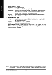
...autodetect the type of Intel Host Embedded Control Interface (HECI) driver from the motherboard driver disk. GA-P35-DS3P Motherboard - 50 - Forces CPU fan to the CPU temperature. Sets PWM mode for a 4-pin CPU fan. Note: The Voltage mode can be controlled by the Intel Quiet System Technology (QST). ...This feature requires the installation of CPU fan installed and sets the optimal CPU fan control mode. (Default) Voltage PWM Sets Voltage mode for a 3-pin CPU fan. A small portion of system memory will be shared when Intel® QST...
...autodetect the type of Intel Host Embedded Control Interface (HECI) driver from the motherboard driver disk. GA-P35-DS3P Motherboard - 50 - Forces CPU fan to the CPU temperature. Sets PWM mode for a 4-pin CPU fan. Note: The Voltage mode can be controlled by the Intel Quiet System Technology (QST). ...This feature requires the installation of CPU fan installed and sets the optimal CPU fan control mode. (Default) Voltage PWM Sets Voltage mode for a 3-pin CPU fan. A small portion of system memory will be shared when Intel® QST...
Manual
Page 51
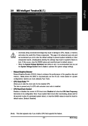
...Tweaker(M.I.T.) CMOS Setup Utility-Copyright (C) 1984-2007 Award Software MB Intelligent Tweaker(M.I.T.) Robust Graphics Booster CPU Clock Ratio (Note) CPU Host Clock Control x CPU Host Frequency (Mhz) PCI Express Frequency (Mhz) C.I.A. 2 Performance Enhance System Memory Multiplier (SPD...DRAM DLL Settings ******** System Voltage Optimized System Voltage Control DDR2 OverVoltage Control PCI-E OverVoltage Control FSB OverVoltage Control (G)MCH OverVoltage Control CPU Voltage Control Normal CPU Vcore ******** [Auto] [18X] [Disabled] 200 [Auto] [Disabled] [Turbo] [Auto] 800 [Option 1] [Manual] ...
...Tweaker(M.I.T.) CMOS Setup Utility-Copyright (C) 1984-2007 Award Software MB Intelligent Tweaker(M.I.T.) Robust Graphics Booster CPU Clock Ratio (Note) CPU Host Clock Control x CPU Host Frequency (Mhz) PCI Express Frequency (Mhz) C.I.A. 2 Performance Enhance System Memory Multiplier (SPD...DRAM DLL Settings ******** System Voltage Optimized System Voltage Control DDR2 OverVoltage Control PCI-E OverVoltage Control FSB OverVoltage Control (G)MCH OverVoltage Control CPU Voltage Control Normal CPU Vcore ******** [Auto] [18X] [Disabled] 200 [Auto] [Disabled] [Turbo] [Auto] 800 [Option 1] [Manual] ...
Manual
Page 52
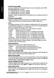
.... PCI Express Frequency (Mhz) Allows you to manually set this item to 333 MHz. Racing Turbo Increases CPU frequency by 7% or 9% depending on system components, when system instability occurs after you overclock the DDR2 memory...CPU frequency be configurable. (Default: Manual) GA-P35-DS3P Motherboard - 52 - English CPU Host Frequency (Mhz) Allows you to manually set in accordance with the CPU specifications. Increases CPU frequency by 9% or 11% depending on CPU loading. Increases CPU frequency by 17% or 19% depending on CPU loading. Full Thrust Increases CPU...
.... PCI Express Frequency (Mhz) Allows you to manually set this item to 333 MHz. Racing Turbo Increases CPU frequency by 7% or 9% depending on system components, when system instability occurs after you overclock the DDR2 memory...CPU frequency be configurable. (Default: Manual) GA-P35-DS3P Motherboard - 52 - English CPU Host Frequency (Mhz) Allows you to manually set in accordance with the CPU specifications. Increases CPU frequency by 9% or 11% depending on CPU loading. Increases CPU frequency by 17% or 19% depending on CPU loading. Full Thrust Increases CPU...
Manual
Page 53
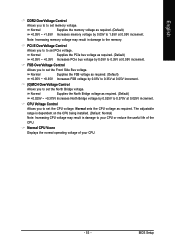
...set PCIe voltage. PCI-E OverVoltage Control Allows you to set the CPU voltage. FSB OverVoltage Control Allows you to to set the Front Side Bus voltage. Normal CPU Vcore Displays the normal operating voltage of the CPU. Normal Supplies the FSB voltage as required. (Default) +0.05V...by 0.05V to 1.55V at 0.05V increment. (G)MCH OverVoltage Control Allows you to set memory voltage. CPU Voltage Control Allows you to 0.35V at 0.05V increment. Normal sets the CPU voltage as required. (Default) +0.025V ~ +0.375V Increases North Bridge voltage by 0.05V to the ...
...set PCIe voltage. PCI-E OverVoltage Control Allows you to set the CPU voltage. FSB OverVoltage Control Allows you to to set the Front Side Bus voltage. Normal CPU Vcore Displays the normal operating voltage of the CPU. Normal Supplies the FSB voltage as required. (Default) +0.05V...by 0.05V to 1.55V at 0.05V increment. (G)MCH OverVoltage Control Allows you to set memory voltage. CPU Voltage Control Allows you to 0.35V at 0.05V increment. Normal sets the CPU voltage as required. (Default) +0.025V ~ +0.375V Increases North Bridge voltage by 0.05V to the ...
Manual
Page 71
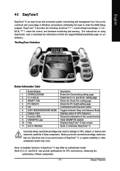
... page Confirmation and Execution button Toggles between Easy and Advance Mode Displays panel of CPU frequency Shows the information of the current function Visits GIGABYTE website Displays EasyTuneTM 5 help screen Quits or minimizes EasyTuneTM 5 Incorrectly doing overclock/overvoltage... may result in Windows environment, eliminating the need to CPU, chipset, or memory and reduce the useful life of these components. -...
... page Confirmation and Execution button Toggles between Easy and Advance Mode Displays panel of CPU frequency Shows the information of the current function Visits GIGABYTE website Displays EasyTuneTM 5 help screen Quits or minimizes EasyTuneTM 5 Incorrectly doing overclock/overvoltage... may result in Windows environment, eliminating the need to CPU, chipset, or memory and reduce the useful life of these components. -...


