Manual
Page 1
GA-P35-DS3P LGA775 socket motherboard for Intel® CoreTM processor family/ Intel® Pentium® processor family/Intel® Celeron® processor family User's Manual Rev. 2002 12ME-P35DS3P-2002R
GA-P35-DS3P LGA775 socket motherboard for Intel® CoreTM processor family/ Intel® Pentium® processor family/Intel® Celeron® processor family User's Manual Rev. 2002 12ME-P35DS3P-2002R
Manual
Page 2
Motherboard GA-P35-DS3P Jul. 20, 2007 Motherboard GA-P35-DS3P Jul. 20, 2007
Motherboard GA-P35-DS3P Jul. 20, 2007 Motherboard GA-P35-DS3P Jul. 20, 2007
Manual
Page 4
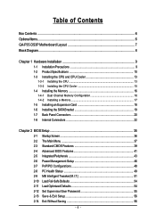
Table of Contents Box Contents ...6 OptionalItems ...6 GA-P35-DS3P Motherboard Layout 7 Block Diagram ...8 Chapter 1 Hardware Installation 9 1-1 Installation Precautions 9 1-2 Product Specifications 10 1-3 Installing the CPU and CPU Cooler 13 1-3-1 Installing the CPU 13 1-3-2 Installing the ...
Table of Contents Box Contents ...6 OptionalItems ...6 GA-P35-DS3P Motherboard Layout 7 Block Diagram ...8 Chapter 1 Hardware Installation 9 1-1 Installation Precautions 9 1-2 Product Specifications 10 1-3 Installing the CPU and CPU Cooler 13 1-3-1 Installing the CPU 13 1-3-2 Installing the ...
Manual
Page 6
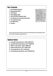
... cable (Part No. 12CF1-1CM001-31R) LPT port cable (Part No. 12CF1-1LP001-01R) 2-port SATA power cable (Part No. 12CF1-2SERPW-01R) - 6 - Box Contents GA-P35-DS3P motherboard Motherboard Driver Disk User's Manual Quick Installation Guide Intel® LGA775 CPU Installation Guide One IDE cable and one floppy disk drive cable Four...
... cable (Part No. 12CF1-1CM001-31R) LPT port cable (Part No. 12CF1-1LP001-01R) 2-port SATA power cable (Part No. 12CF1-2SERPW-01R) - 6 - Box Contents GA-P35-DS3P motherboard Motherboard Driver Disk User's Manual Quick Installation Guide Intel® LGA775 CPU Installation Guide One IDE cable and one floppy disk drive cable Four...
Manual
Page 8
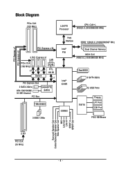
... 8111B Switch x1 PCI Express Bus 2 SATA 3Gb/s ATA-133/100/66/ 33 IDE Channel PCI Bus GIGABYTE SATA2 TSB43AB23 3 IEEE 1394a Host Interface DDR2 1200(O.C.)/1066/800/667 MHz Intel® Dual Channel Memory P35 MCH CLK (400(O.C.)/333/266/200 MHz) Intel® ICH9R CODEC Dual BIOS 6 SATA 3Gb/s 12...
... 8111B Switch x1 PCI Express Bus 2 SATA 3Gb/s ATA-133/100/66/ 33 IDE Channel PCI Bus GIGABYTE SATA2 TSB43AB23 3 IEEE 1394a Host Interface DDR2 1200(O.C.)/1066/800/667 MHz Intel® Dual Channel Memory P35 MCH CLK (400(O.C.)/333/266/200 MHz) Intel® ICH9R CODEC Dual BIOS 6 SATA 3Gb/s 12...
Manual
Page 10
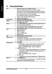
...GIGABYTE SATA2 chip: - 1 x IDE connector supporting ATA-133/100/66/33 and up to 2 IDE devices - 2 x SATA 3Gb/s connectors (GSATAII0, GSATAII1) supporting up to 6 SATA 3Gb/s devices - TSB43AB23 chip Š Up to 3 IEEE 1394a ports (2 on the back panel, 1 via the IEEE 1394 bracket connected to the internal IEEE 1394 headers) GA-P35-DS3P... Motherboard - 10 - the PCIE_16_2 supports x4.) Š 3 x PCI Express x1 slots (share with CPU Š 1600(O.C.)/1333/1066/800 MHz FSB Š North Bridge: Intel® P35 Express Chipset Š South Bridge...
...GIGABYTE SATA2 chip: - 1 x IDE connector supporting ATA-133/100/66/33 and up to 2 IDE devices - 2 x SATA 3Gb/s connectors (GSATAII0, GSATAII1) supporting up to 6 SATA 3Gb/s devices - TSB43AB23 chip Š Up to 3 IEEE 1394a ports (2 on the back panel, 1 via the IEEE 1394 bracket connected to the internal IEEE 1394 headers) GA-P35-DS3P... Motherboard - 10 - the PCIE_16_2 supports x4.) Š 3 x PCI Express x1 slots (share with CPU Š 1600(O.C.)/1333/1066/800 MHz FSB Š North Bridge: Intel® P35 Express Chipset Š South Bridge...
Manual
Page 12
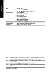
GA-P35-DS3P Motherboard - 12 - English BIOS Unique Features Bundled Software Operating System Form Factor Š 2 x 8 Mbit flash Š Use of licensed AWARD BIOS Š PnP 1.0a, DMI 2.0, ...
GA-P35-DS3P Motherboard - 12 - English BIOS Unique Features Bundled Software Operating System Form Factor Š 2 x 8 Mbit flash Š Use of licensed AWARD BIOS Š PnP 1.0a, DMI 2.0, ...
Manual
Page 14
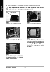
... off the computer and unplug the power cord from the power outlet to prevent damage to correctly install the CPU into the motherboard CPU socket. GA-P35-DS3P Motherboard - 14 - Step 3: Lift the metal load plate on the CPU socket. English B. Step 4: Hold the CPU with the socket alignment keys) and gently insert...
... off the computer and unplug the power cord from the power outlet to prevent damage to correctly install the CPU into the motherboard CPU socket. GA-P35-DS3P Motherboard - 14 - Step 3: Lift the metal load plate on the CPU socket. English B. Step 4: Hold the CPU with the socket alignment keys) and gently insert...
Manual
Page 16
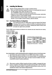
...if only one direction. When memory modules of the same capacity, brand, speed, and chips be used . (Go to GIGABYTE's website for optimum performance. Intel® Flex Memory Technology offers greater flexibility to upgrade by allowing different memory sizes to chipset...following : Channel 0: DDRII1, DDRII2 Channel 1: DDRII3, DDRII4 Dual Channel Memory Configurations Table DDRII1 DDRII2 DDRII3 Two Modules DS/SS - - GA-P35-DS3P Motherboard - 16 - A memory module can be installed in Dual Channel mode/performance. English 1-4 Installing the Memory Read the following guidelines...
...if only one direction. When memory modules of the same capacity, brand, speed, and chips be used . (Go to GIGABYTE's website for optimum performance. Intel® Flex Memory Technology offers greater flexibility to upgrade by allowing different memory sizes to chipset...following : Channel 0: DDRII1, DDRII2 Channel 1: DDRII3, DDRII4 Dual Channel Memory Configurations Table DDRII1 DDRII2 DDRII3 Two Modules DS/SS - - GA-P35-DS3P Motherboard - 16 - A memory module can be installed in Dual Channel mode/performance. English 1-4 Installing the Memory Read the following guidelines...
Manual
Page 18
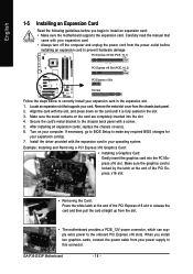
... to release the card and then pull the card straight up from the chassis back panel. 2. After installing all expansion cards, replace the chassis cover(s). 6. GA-P35-DS3P Motherboard - 18 - Turn on your expansion card(s). 7. If necessary, go to BIOS Setup to make any required BIOS changes for your computer. PCI Express x16...
... to release the card and then pull the card straight up from the chassis back panel. 2. After installing all expansion cards, replace the chassis cover(s). 6. GA-P35-DS3P Motherboard - 18 - Turn on your expansion card(s). 7. If necessary, go to BIOS Setup to make any required BIOS changes for your computer. PCI Express x16...
Manual
Page 20
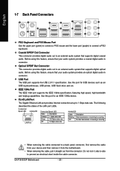
Before using this feature, ensure that your audio system provides an optical digital audio in connector. GA-P35-DS3P Motherboard - 20 - Before using this feature, ensure that your device and then remove it from the motherboard. • When removing the cable, pull it side ...
Before using this feature, ensure that your audio system provides an optical digital audio in connector. GA-P35-DS3P Motherboard - 20 - Before using this feature, ensure that your device and then remove it from the motherboard. • When removing the cable, pull it side ...
Manual
Page 22
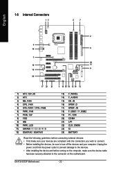
...) SPDIF_IN 18) F_USB1 / F_USB2 19) F1_1394 20) COMA 21) LPT 22) CLR_CMOS 23) CI 24) BATTERY Read the following guidelines before turning on the motherboard. GA-P35-DS3P Motherboard - 22 - Unplug the power cord from the power outlet to prevent damage to the devices. • After installing the device and before connecting external...
...) SPDIF_IN 18) F_USB1 / F_USB2 19) F1_1394 20) COMA 21) LPT 22) CLR_CMOS 23) CI 24) BATTERY Read the following guidelines before turning on the motherboard. GA-P35-DS3P Motherboard - 22 - Unplug the power cord from the power outlet to prevent damage to the devices. • After installing the device and before connecting external...
Manual
Page 24
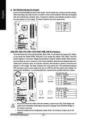
... header. The black connector wire is the ground wire. Definition 1 GND 2 +12V / Speed Control 3 Sense 4 Speed Control 1 PWR_FAN 1 SYS_FAN1 PWR_FAN / SYS_FAN1 : Pin No. Pin No. GA-P35-DS3P Motherboard - 24 - A red power connector wire indicates a positive connection and requires a +12V voltage. When connecting a fan cable, be installed inside the chassis. 1 CPU_FAN 1 SYS_FAN2 CPU_FAN...
... header. The black connector wire is the ground wire. Definition 1 GND 2 +12V / Speed Control 3 Sense 4 Speed Control 1 PWR_FAN 1 SYS_FAN1 PWR_FAN / SYS_FAN1 : Pin No. Pin No. GA-P35-DS3P Motherboard - 24 - A red power connector wire indicates a positive connection and requires a +12V voltage. When connecting a fan cable, be installed inside the chassis. 1 CPU_FAN 1 SYS_FAN2 CPU_FAN...

Manual
Page 26
The LED keeps blinking when the system is in S1 sleep state. System Status LED S0 On S1 Blinking S3/S4/S5 Off GA-P35-DS3P Motherboard - 26 - The LED is off when the system is in S3/S4 sleep state or powered off (S5). The LED is on the connector. ...
The LED keeps blinking when the system is in S1 sleep state. System Status LED S0 On S1 Blinking S3/S4/S5 Off GA-P35-DS3P Motherboard - 26 - The LED is off when the system is in S3/S4 sleep state or powered off (S5). The LED is on the connector. ...
Manual
Page 28
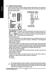
... speaker on when the hard drive is in different patterns to this header, make sure the wire assignments and the pin assignments are matched correctly. GA-P35-DS3P Motherboard - 28 - English 13) F_PANEL (Front Panel Header) Connect the power switch, reset switch, speaker and system status indicator on the chassis front panel. You...
... speaker on when the hard drive is in different patterns to this header, make sure the wire assignments and the pin assignments are matched correctly. GA-P35-DS3P Motherboard - 28 - English 13) F_PANEL (Front Panel Header) Connect the power switch, reset switch, speaker and system status indicator on the chassis front panel. You...
Manual
Page 30
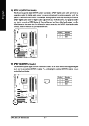
... the manual for digital audio output from the HDMI display at the same time. For purchasing the optional S/PDIF in cable. Definition 1 Power 1 2 SPDIFI 3 GND GA-P35-DS3P Motherboard - 30 - English 16) SPDIF_O (S/PDIF Out Header) This header supports digital S/PDIF out and connects a S/PDIF digital audio cable (provided by expansion cards) for...
... the manual for digital audio output from the HDMI display at the same time. For purchasing the optional S/PDIF in cable. Definition 1 Power 1 2 SPDIFI 3 GND GA-P35-DS3P Motherboard - 30 - English 16) SPDIF_O (S/PDIF Out Header) This header supports digital S/PDIF out and connects a S/PDIF digital audio cable (provided by expansion cards) for...

Manual
Page 32
... 16 17 18 19 20 21 22 23 24 25 26 Definition GND PD6 GND PD7 GND ACKGND BUSY GND PE No Pin SLCT GND GA-P35-DS3P Motherboard - 32 - English 20) COMA (Serial Port Header) The COMA header can provide one serial port via an optional LPT port cable...
... 16 17 18 19 20 21 22 23 24 25 26 Definition GND PD6 GND PD7 GND ACKGND BUSY GND PE No Pin SLCT GND GA-P35-DS3P Motherboard - 32 - English 20) COMA (Serial Port Header) The COMA header can provide one serial port via an optional LPT port cable...
Manual
Page 34
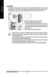
... if you are not able to replace the battery by removing the battery: 1. Gently remove the battery from the battery holder and wait for one . GA-P35-DS3P Motherboard - 34 - Replace the battery when the battery voltage drops to a low level, or the CMOS values may not be accurate or may clear the...
... if you are not able to replace the battery by removing the battery: 1. Gently remove the battery from the battery holder and wait for one . GA-P35-DS3P Motherboard - 34 - Replace the battery when the battery voltage drops to a low level, or the CMOS values may not be accurate or may clear the...
Manual
Page 36
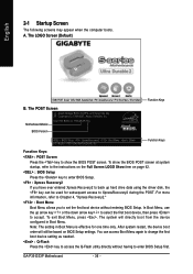
...to back up arrow key < > or the down arrow key< > to select the first boot device, then press to XpressRecovery2 during the POST. GA-P35-DS3P Motherboard - 36 - To show the BIOS POST screen. The LOGO Screen (Default) :POST Screen :BIOS Setup/Q-Flash :XpressRecovery2 :Boot Menu :Qflash ... the first boot device without having to enter BIOS Setup first. Motherboard Model BIOS Version Intel P35 BIOS for P35-DS3P F5g . . . . : BIOS Setup : XpressRecovery2 : Boot Menu : Qflash 07/18/2007-P35-ICH9-6A79OG0HC-00 Function Keys Function Keys: : POST Screen Press the key to show the...
...to back up arrow key < > or the down arrow key< > to select the first boot device, then press to XpressRecovery2 during the POST. GA-P35-DS3P Motherboard - 36 - To show the BIOS POST screen. The LOGO Screen (Default) :POST Screen :BIOS Setup/Q-Flash :XpressRecovery2 :Boot Menu :Qflash ... the first boot device without having to enter BIOS Setup first. Motherboard Model BIOS Version Intel P35 BIOS for P35-DS3P F5g . . . . : BIOS Setup : XpressRecovery2 : Boot Menu : Qflash 07/18/2007-P35-ICH9-6A79OG0HC-00 Function Keys Function Keys: : POST Screen Press the key to show the...
Manual
Page 38
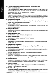
... system operations. „ Set Supervisor Password Change, set , or disable password. First enter the profile name (to erase the default profile name, use this task.) GA-P35-DS3P Motherboard - 38 - An user password only allows you can use the SPACE key) and then press to complete. ` F12 : Load CMOS from a profile created before...
... system operations. „ Set Supervisor Password Change, set , or disable password. First enter the profile name (to erase the default profile name, use this task.) GA-P35-DS3P Motherboard - 38 - An user password only allows you can use the SPACE key) and then press to complete. ` F12 : Load CMOS from a profile created before...
