Manual
Page 1
GA-P35-DS3R/ GA-P35-DS3/ GA-P35-S3 LGA775 socket motherboard for Intel® CoreTM processor family/ Intel® Pentium® processor family/Intel® Celeron® processor family User's Manual Rev. 2002 12ME-P35DS3R-2002R
GA-P35-DS3R/ GA-P35-DS3/ GA-P35-S3 LGA775 socket motherboard for Intel® CoreTM processor family/ Intel® Pentium® processor family/Intel® Celeron® processor family User's Manual Rev. 2002 12ME-P35DS3R-2002R
Manual
Page 2
Motherboard GA-P35-DS3R/GA-P35-DS3/GA-P35-S3 Jul. 25, 2007 Motherboard GA-P35-DS3R/GA-P35-DS3/ GA-P35-S3 Jul. 25, 2007
Motherboard GA-P35-DS3R/GA-P35-DS3/GA-P35-S3 Jul. 25, 2007 Motherboard GA-P35-DS3R/GA-P35-DS3/ GA-P35-S3 Jul. 25, 2007
Manual
Page 4
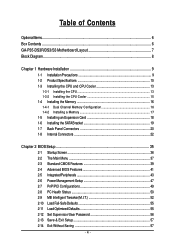
Table of Contents OptionalItems ...6 Box Contents ...6 GA-P35-DS3R/DS3/S3 Motherboard Layout 7 Block Diagram ...8 Chapter 1 Hardware Installation 9 1-1 Installation Precautions 9 1-2 Product Specifications 10 1-3 Installing the CPU and CPU Cooler 13 1-3-1 Installing the CPU 13 1-3-2 Installing the ...
Table of Contents OptionalItems ...6 Box Contents ...6 GA-P35-DS3R/DS3/S3 Motherboard Layout 7 Block Diagram ...8 Chapter 1 Hardware Installation 9 1-1 Installation Precautions 9 1-2 Product Specifications 10 1-3 Installing the CPU and CPU Cooler 13 1-3-1 Installing the CPU 13 1-3-2 Installing the ...
Manual
Page 6
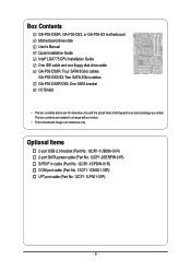
... (Part No. 12CF1-1LP001-01R) - 6 - Box Contents GA-P35-DS3R, GA-P35-DS3, or GA-P35-S3 motherboard Motherboard driver disk User's Manual Quick Installation Guide Intel® LGA775 CPU Installation Guide One IDE cable and one floppy disk drive cable GA-P35-DS3R: Four SATA 3Gb/s cables GA-P35-DS3/S3: Two SATA 3Gb/s cables GA-P35-DS3R/DS3: One SATA bracket I/O Shield • The box...
... (Part No. 12CF1-1LP001-01R) - 6 - Box Contents GA-P35-DS3R, GA-P35-DS3, or GA-P35-S3 motherboard Motherboard driver disk User's Manual Quick Installation Guide Intel® LGA775 CPU Installation Guide One IDE cable and one floppy disk drive cable GA-P35-DS3R: Four SATA 3Gb/s cables GA-P35-DS3/S3: Two SATA 3Gb/s cables GA-P35-DS3R/DS3: One SATA bracket I/O Shield • The box...
Manual
Page 7
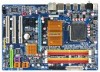
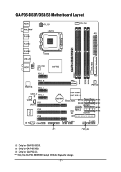
... GA-P35-DS3. GA-P35-DS3R/DS3/S3 Motherboard Layout KB_MS RCA_SPDIF R_USB1 R_USB2 R_USB3 ATX_12V LGA775 CPU_FAN ATX GA-P35-DS3R/DS3/S3 DDRII1 USB_LAN F_AUDIO AUDIO SYS_FAN1 PCIE_3 PCIE_16 RTL8111B PCIE_1 SPDIF_O PCIE_2 CODEC PCI1 SPDIF_I PCI2 IT8718 CD_IN PCI3 COMA Intel® P35 FDD DDRII3 DDRII4 DDRII2 PWR_FAN BATTERY Intel® ICH9R Intel® ICH9 CLR_CMOS SATAII2 SATAII3 GSATAII0 GIGABYTE...
... GA-P35-DS3. GA-P35-DS3R/DS3/S3 Motherboard Layout KB_MS RCA_SPDIF R_USB1 R_USB2 R_USB3 ATX_12V LGA775 CPU_FAN ATX GA-P35-DS3R/DS3/S3 DDRII1 USB_LAN F_AUDIO AUDIO SYS_FAN1 PCIE_3 PCIE_16 RTL8111B PCIE_1 SPDIF_O PCIE_2 CODEC PCI1 SPDIF_I PCI2 IT8718 CD_IN PCI3 COMA Intel® P35 FDD DDRII3 DDRII4 DDRII2 PWR_FAN BATTERY Intel® ICH9R Intel® ICH9 CLR_CMOS SATAII2 SATAII3 GSATAII0 GIGABYTE...
Manual
Page 8
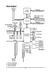
Only for GA-P35-S3. - 8 - Only for GA-P35-DS3. Block Diagram PCIe CLK (100 MHz) LGA775 Processor CPU CLK+/(400(O.C.)/333/266/200 MHz) Host Interface DDR2 1200(O.C.)/1066/ 800/667 MHz PCI Express x16 2 SATA 3Gb/s ATA-133/100/66/33 IDE Channel GIGABYTE SATA2 LAN RJ45 RTL 8111B x1 PCI Express Bus x1 3... PCI Express x1 x 1 x 1 x 1 PCIe CLK (100 MHz) PCI Bus Intel® P35 Intel® ICH9R Intel® ICH9 CODEC Dual Channel Memory MCH CLK (400(O.C.)/...
Only for GA-P35-S3. - 8 - Only for GA-P35-DS3. Block Diagram PCIe CLK (100 MHz) LGA775 Processor CPU CLK+/(400(O.C.)/333/266/200 MHz) Host Interface DDR2 1200(O.C.)/1066/ 800/667 MHz PCI Express x16 2 SATA 3Gb/s ATA-133/100/66/33 IDE Channel GIGABYTE SATA2 LAN RJ45 RTL 8111B x1 PCI Express Bus x1 3... PCI Express x1 x 1 x 1 x 1 PCIe CLK (100 MHz) PCI Bus Intel® P35 Intel® ICH9R Intel® ICH9 CODEC Dual Channel Memory MCH CLK (400(O.C.)/...
Manual
Page 10
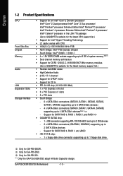
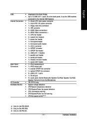
...GA-P35-DS3. GA-P35-DS3R/DS3/S3 Motherboard - 10 - "*" Only the GA-P35-DS3R/DS3 adopt All-Solid Capacitor design. Only for GA-P35-S3. Support for SATA RAID 0, RAID 1, and JBOD Š iTE IT8718 chip: - 1 x floppy disk drive connector supporting up to 2 SATA 3Gb/s devices - Support for SATA RAID 0, RAID 1, RAID 5, and RAID 10 Š GIGABYTE...Edition/Intel® Pentium® 4 processor/ Intel® Celeron® processor in the LGA 775 package (Go to GIGABYTE's website for the latest CPU support list.) Š Support for Intel® Hyper-Threading Technology Š L2 cache ...
...GA-P35-DS3. GA-P35-DS3R/DS3/S3 Motherboard - 10 - "*" Only the GA-P35-DS3R/DS3 adopt All-Solid Capacitor design. Only for GA-P35-S3. Support for SATA RAID 0, RAID 1, and JBOD Š iTE IT8718 chip: - 1 x floppy disk drive connector supporting up to 2 SATA 3Gb/s devices - Support for SATA RAID 0, RAID 1, RAID 5, and RAID 10 Š GIGABYTE...Edition/Intel® Pentium® 4 processor/ Intel® Celeron® processor in the LGA 775 package (Go to GIGABYTE's website for the latest CPU support list.) Š Support for Intel® Hyper-Threading Technology Š L2 cache ...
Manual
Page 11
...; CPU/System/Power fan speed detection Š CPU overheating warning Š CPU/System/Power fan fail warning Š CPU fan speed control (Note 3) Only for GA-P35-DS3. Only for GA-P35-DS3R. Hardware Installation Only for GA-P35-S3. - 11 -
...; CPU/System/Power fan speed detection Š CPU overheating warning Š CPU/System/Power fan fail warning Š CPU fan speed control (Note 3) Only for GA-P35-DS3. Only for GA-P35-DS3R. Hardware Installation Only for GA-P35-S3. - 11 -
Manual
Page 12
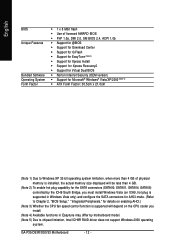
GA-P35-DS3R/DS3/S3 Motherboard - 12 - English BIOS Unique Features Bundled Software Operating System Form Factor Š 1 x 8 Mbit flash Š Use of licensed AWARD BIOS Š PnP 1.0a, DMI 2.0, ...
GA-P35-DS3R/DS3/S3 Motherboard - 12 - English BIOS Unique Features Bundled Software Operating System Form Factor Š 1 x 8 Mbit flash Š Use of licensed AWARD BIOS Š PnP 1.0a, DMI 2.0, ...
Manual
Page 14
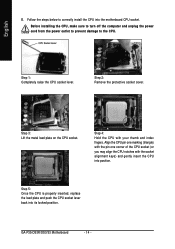
... socket lever. Step 5: Once the CPU is properly inserted, replace the load plate and push the CPU socket lever back into the motherboard CPU socket. GA-P35-DS3R/DS3/S3 Motherboard - 14 - Step 3: Lift the metal load plate on the CPU socket. Step 2: Remove the protective socket cover. Follow the steps below to the...
... socket lever. Step 5: Once the CPU is properly inserted, replace the load plate and push the CPU socket lever back into the motherboard CPU socket. GA-P35-DS3R/DS3/S3 Motherboard - 14 - Step 3: Lift the metal load plate on the CPU socket. Step 2: Remove the protective socket cover. Follow the steps below to the...
Manual
Page 16
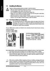
...power cord from the power outlet before installing the memory in Dual Channel mode/performance. Dual Channel mode cannot be enabled if only one direction. GA-P35-DS3R/DS3/S3 Motherboard - 16 - DS/SS DS/SS (SS=Single-Sided, DS=Double-Sided, "- -"=No Memory) DDRII1 DDRII2 DDRII3 DDRII4 Due to ...during the POST. If you begin to install the memory: • Make sure that memory of different capacity and chips are unable to GIGABYTE's website for optimum performance. The four DDR2 memory sockets are divided into two channels and each channel has two memory sockets as following: ...
...power cord from the power outlet before installing the memory in Dual Channel mode/performance. Dual Channel mode cannot be enabled if only one direction. GA-P35-DS3R/DS3/S3 Motherboard - 16 - DS/SS DS/SS (SS=Single-Sided, DS=Double-Sided, "- -"=No Memory) DDRII1 DDRII2 DDRII3 DDRII4 Due to ...during the POST. If you begin to install the memory: • Make sure that memory of different capacity and chips are unable to GIGABYTE's website for optimum performance. The four DDR2 memory sockets are divided into two channels and each channel has two memory sockets as following: ...
Manual
Page 18
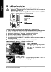
Remove the metal slot cover from the slot. GA-P35-DS3R/DS3/S3 Motherboard - 18 - English 1-5 Installing an Expansion Card Read the following guidelines before installing an expansion card to prevent hardware damage. Make sure the metal contacts ...
Remove the metal slot cover from the slot. GA-P35-DS3R/DS3/S3 Motherboard - 18 - English 1-5 Installing an Expansion Card Read the following guidelines before installing an expansion card to prevent hardware damage. Make sure the metal contacts ...
Manual
Page 20
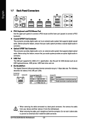
RJ-45 LAN Port The Gigabit Ethernet LAN port provides Internet connection at up to an external audio system that supports digital coaxial audio. GA-P35-DS3R/DS3/S3 Motherboard - 20 - Before using this feature, ensure that your device and then remove it from the connector. Coaxial S/PDIF Out Connector This connector provides digital ...
RJ-45 LAN Port The Gigabit Ethernet LAN port provides Internet connection at up to an external audio system that supports digital coaxial audio. GA-P35-DS3R/DS3/S3 Motherboard - 20 - Before using this feature, ensure that your device and then remove it from the connector. Coaxial S/PDIF Out Connector This connector provides digital ...
Manual
Page 22
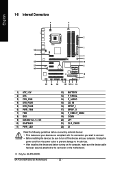
GA-P35-DS3R/DS3/S3 Motherboard - 22 - Unplug the power cord from the power outlet to prevent damage to the devices. • After installing the device and before connecting external ... devices are compliant with the connectors you wish to connect. • Before installing the devices, be sure to the connector on the motherboard. Only for GA-P35-DS3R.
GA-P35-DS3R/DS3/S3 Motherboard - 22 - Unplug the power cord from the power outlet to prevent damage to the devices. • After installing the device and before connecting external ... devices are compliant with the connectors you wish to connect. • Before installing the devices, be sure to the connector on the motherboard. Only for GA-P35-DS3R.
Manual
Page 24
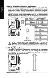
... system may result in the correct orientation. The types of the connector and the floppy disk drive cable. The pin 1 of different color. 34 33 GA-P35-DS3R/DS3/S3 Motherboard 2 1 - 24 - Each fan header supplies a +12V power voltage and possesses a foolproof insertion design. CPU_FAN (For PCB rev. 2.0): Pin No. Do not place a jumper...
... system may result in the correct orientation. The types of the connector and the floppy disk drive cable. The pin 1 of different color. 34 33 GA-P35-DS3R/DS3/S3 Motherboard 2 1 - 24 - Each fan header supplies a +12V power voltage and possesses a foolproof insertion design. CPU_FAN (For PCB rev. 2.0): Pin No. Do not place a jumper...
Manual
Page 26
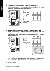
... 0 or RAID 1 configuration requires at least two hard drives. Only for GA-P35-DS3. Refer to your SATA hard drive. GA-P35-DS3R/DS3/S3 Motherboard - 26 - Pin No. Only for GA-P35-S3. The GIGABYTE SATA2 controller supports RAID 0 and RAID 1. English 9) SATAII0/1/4/5 (SATA 3Gb/s Connectors, Controlled by GIGABYTE SATA2, Purple) The SATA connectors conform to SATA 3Gb/s standard and are...
... 0 or RAID 1 configuration requires at least two hard drives. Only for GA-P35-DS3. Refer to your SATA hard drive. GA-P35-DS3R/DS3/S3 Motherboard - 26 - Pin No. Only for GA-P35-S3. The GIGABYTE SATA2 controller supports RAID 0 and RAID 1. English 9) SATAII0/1/4/5 (SATA 3Gb/s Connectors, Controlled by GIGABYTE SATA2, Purple) The SATA connectors conform to SATA 3Gb/s standard and are...
Manual
Page 27
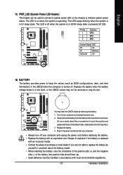
... sleep state or powered off (S5). Pin No. System Status LED S0 On S1 Blinking S3/S4/S5 Off 12) BATTERY The battery provides power to a low level, or the CMOS values may not be accurate or may clear the CMOS ...
... sleep state or powered off (S5). Pin No. System Status LED S0 On S1 Blinking S3/S4/S5 Off 12) BATTERY The battery provides power to a low level, or the CMOS values may not be accurate or may clear the CMOS ...
Manual
Page 28
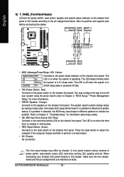
... LED is off when the system is detected at system startup. One single short beep will be heard if no problem is in S3/S4/S5 Off S3/S4 sleep state or powered off your chassis front panel module to this header according to the pin assignments below. Message/Power/ Power... about beep codes. • HD (IDE Hard Drive Activity LED, Blue) Connects to the power status indicator on when the hard drive is operating. GA-P35-DS3R/DS3/S3 Motherboard - 28 - RESRES+ NC IDE Hard Disk Reset Active LED Switch • MSG (Message/Power/Sleep LED, Yellow): System Status LED Connects to...
... LED is off when the system is detected at system startup. One single short beep will be heard if no problem is in S3/S4/S5 Off S3/S4 sleep state or powered off your chassis front panel module to this header according to the pin assignments below. Message/Power/ Power... about beep codes. • HD (IDE Hard Drive Activity LED, Blue) Connects to the power status indicator on when the hard drive is operating. GA-P35-DS3R/DS3/S3 Motherboard - 28 - RESRES+ NC IDE Hard Disk Reset Active LED Switch • MSG (Message/Power/Sleep LED, Yellow): System Status LED Connects to...
Manual
Page 30
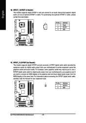
... (S/PDIF In Header) This header supports digital S/PDIF in and can connect to certain expansion cards like graphics cards and sound cards. Definition 1 SPDIFO 2 GND GA-P35-DS3R/DS3/S3 Motherboard - 30 - For example, some graphics cards may require you to use a S/PDIF digital audio cable for digital audio output from your motherboard to...
... (S/PDIF In Header) This header supports digital S/PDIF in and can connect to certain expansion cards like graphics cards and sound cards. Definition 1 SPDIFO 2 GND GA-P35-DS3R/DS3/S3 Motherboard - 30 - For example, some graphics cards may require you to use a S/PDIF digital audio cable for digital audio output from your motherboard to...
Manual
Page 32
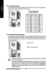
... turning on the two pins to temporarily short the two pins or use a metal object like a screwdriver to remove the jumper cap from the jumper. GA-P35-DS3R/DS3/S3 Motherboard - 32 - English 20) LPT (Parallel Port Header) The LPT header can provide one parallel port via an optional LPT port cable. For purchasing...
... turning on the two pins to temporarily short the two pins or use a metal object like a screwdriver to remove the jumper cap from the jumper. GA-P35-DS3R/DS3/S3 Motherboard - 32 - English 20) LPT (Parallel Port Header) The LPT header can provide one parallel port via an optional LPT port cable. For purchasing...

