Manual
Page 1
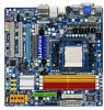
GA-MA785GPM-UD2H/ GA-MA785GM-UD2H/ GA-MA785GM-US2H AM2+/AM2 socket motherboard for AMD Phenom™ II processor/ AMD Phenom™ processor/ AMD Athlon™ II processor/ AMD Athlon™ processor/ AMD Sempron™ processor User's Manual Rev. 1001 12ME-MA785M2-1001R
GA-MA785GPM-UD2H/ GA-MA785GM-UD2H/ GA-MA785GM-US2H AM2+/AM2 socket motherboard for AMD Phenom™ II processor/ AMD Phenom™ processor/ AMD Athlon™ II processor/ AMD Athlon™ processor/ AMD Sempron™ processor User's Manual Rev. 1001 12ME-MA785M2-1001R
Manual
Page 3
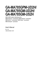
For product-related information, check on our website at: http://www.gigabyte.com.tw Identifying Your Motherboard Revision The revision number on your motherboard revision before updating motherboard BIOS, drivers, or when looking for technical information. Check your motherboard looks like this manual is protected by any means without prior notice. Changes to their respective owners. No...
For product-related information, check on our website at: http://www.gigabyte.com.tw Identifying Your Motherboard Revision The revision number on your motherboard revision before updating motherboard BIOS, drivers, or when looking for technical information. Check your motherboard looks like this manual is protected by any means without prior notice. Changes to their respective owners. No...
Manual
Page 6
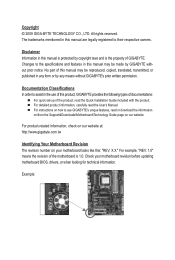
... cable (Part No. 12CF1-1CM001-3*R) LPT port cable (Part No. 12CF1-1LP001-0*R) - 6 - The box contents are for reference only. Box Contents GA-MA785GPM-UD2H, GA-MA785GM-UD2H, or GA-MA785GM-US2H motherboard Motherboard driver disk User's Manual Quick Installation Guide One IDE cable Two SATA 3Gb/s cables I/O Shield • The box contents above are subject to change without notice...
... cable (Part No. 12CF1-1CM001-3*R) LPT port cable (Part No. 12CF1-1LP001-0*R) - 6 - The box contents are for reference only. Box Contents GA-MA785GPM-UD2H, GA-MA785GM-UD2H, or GA-MA785GM-US2H motherboard Motherboard driver disk User's Manual Quick Installation Guide One IDE cable Two SATA 3Gb/s cables I/O Shield • The box contents above are subject to change without notice...
Manual
Page 9
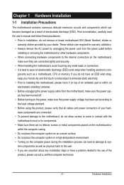
...power, make sure the power supply has been turned off. • Before turning on the computer power during the installation process can become damaged as a motherboard, CPU or memory. ponents such as a result of the product, please consult a certified computer technician. - 9 - These stickers are required for warranty... the product, please verify that all cables and power connectors of your dealer. Prior to installation, carefully read the user's manual and follow these procedures: • Prior to wear an electrostatic discharge (ESD) wrist strap when handling electronic com-
...power, make sure the power supply has been turned off. • Before turning on the computer power during the installation process can become damaged as a motherboard, CPU or memory. ponents such as a result of the product, please consult a certified computer technician. - 9 - These stickers are required for warranty... the product, please verify that all cables and power connectors of your dealer. Prior to installation, carefully read the user's manual and follow these procedures: • Prior to wear an electrostatic discharge (ESD) wrist strap when handling electronic com-

Manual
Page 15
Step 3: Hook the CPU cooler clip to the CPU fan header (CPU_FAN) on the motherboard. Step 4: Turn the cam handle from the left side to the right side (as the example.) Step 1: Apply an even and thin layer of thermal ... cooler may adhere to correctly install the CPU cooler on the CPU. (The following procedure uses the GIGABYTE cooler as the picture above shows) to lock into place. (Refer to your CPU cooler installation manual for instructions on installing the cooler.) Step 5: Finally, attach the power connector of the CPU cooler to...
Step 3: Hook the CPU cooler clip to the CPU fan header (CPU_FAN) on the motherboard. Step 4: Turn the cam handle from the left side to the right side (as the example.) Step 1: Apply an even and thin layer of thermal ... cooler may adhere to correctly install the CPU cooler on the CPU. (The following procedure uses the GIGABYTE cooler as the picture above shows) to lock into place. (Refer to your CPU cooler installation manual for instructions on installing the cooler.) Step 5: Finally, attach the power connector of the CPU cooler to...
Manual
Page 18
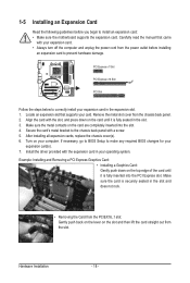
...chassis back panel with the slot, and press down on the slot and then lift the card straight out from the slot. Carefully read the manual that supports your computer. Remove the metal slot cover from the PCIEX16_1 slot: Gently push back on the lever on the top edge of the... to make any required BIOS changes for your expansion card(s). 7. If necessary, go to BIOS Setup to install an expansion card: • Make sure the motherboard supports the expansion card. PCI Express x1 Slot PCI Express x16 Slot PCI Slot Follow the steps below to prevent hardware damage. After installing all...
...chassis back panel with the slot, and press down on the slot and then lift the card straight out from the slot. Carefully read the manual that supports your computer. Remove the metal slot cover from the PCIEX16_1 slot: Gently push back on the lever on the top edge of the... to make any required BIOS changes for your expansion card(s). 7. If necessary, go to BIOS Setup to install an expansion card: • Make sure the motherboard supports the expansion card. PCI Express x1 Slot PCI Express x16 Slot PCI Slot Follow the steps below to prevent hardware damage. After installing all...
Manual
Page 33
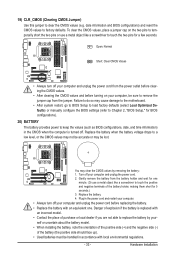
... to remove the jumper cap from the jumper. Failure to do so may cause damage to the motherboard. • After system restart, go to BIOS Setup to load factory defaults (select Load Optimized Defaults) or manually configure the BIOS settings (refer to touch the positive and negative terminals of the battery (the...
... to remove the jumper cap from the jumper. Failure to do so may cause damage to the motherboard. • After system restart, go to BIOS Setup to load factory defaults (select Load Optimized Defaults) or manually configure the BIOS settings (refer to touch the positive and negative terminals of the battery (the...
Manual
Page 61
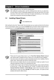
...drivers. • After the drivers are recommended to restart your system automatically during the driver installation. Or click Install Single Items to manually select the drivers you wish to do so may affect the driver installation. • Some device drivers will then autodetect and install the... USB 2.0 driver.) - 61 - After installing the SP1 (or later), if a question mark still exists in Universal Serial Bus Controller in the motherboard driver disk. • For USB 2.0 driver support under the Windows XP operating system, please install the Windows XP Service Pack 1 or later. ...
...drivers. • After the drivers are recommended to restart your system automatically during the driver installation. Or click Install Single Items to manually select the drivers you wish to do so may affect the driver installation. • Some device drivers will then autodetect and install the... USB 2.0 driver.) - 61 - After installing the SP1 (or later), if a question mark still exists in Universal Serial Bus Controller in the motherboard driver disk. • For USB 2.0 driver support under the Windows XP operating system, please install the Windows XP Service Pack 1 or later. ...
Manual
Page 62
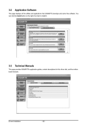
You can click the Install button on the right of an item to install it. 3-3 Technical Manuals This page provides GIGABYTE's application guides, content descriptions for this driver disk, and the motherboard manuals. 3-2 Application Software This page displays all the utilities and applications that GIGABYTE develops and some free software. Drivers Installation - 62 -
You can click the Install button on the right of an item to install it. 3-3 Technical Manuals This page provides GIGABYTE's application guides, content descriptions for this driver disk, and the motherboard manuals. 3-2 Application Software This page displays all the utilities and applications that GIGABYTE develops and some free software. Drivers Installation - 62 -

Manual
Page 68
... main BIOS. 4-2 BIOS Update Utilities GIGABYTE motherboards provide two unique BIOS update tools, Q-Flash™ and @BIOS™. Additionally, this motherboard features the DualBIOS™ design, which... enhances protection for the safety and stability of system safety, users cannot update the backup BIOS manually. However, if...physical BIOS chip. However, if the BIOS update file is DualBIOS™? Unique Features - 68 - GA-MA785GPM-UD2H E3c . . . . : BIOS Setup : XpressRecovery2 : Boot Menu : Qflash 06/05/2009-...
... main BIOS. 4-2 BIOS Update Utilities GIGABYTE motherboards provide two unique BIOS update tools, Q-Flash™ and @BIOS™. Additionally, this motherboard features the DualBIOS™ design, which... enhances protection for the safety and stability of system safety, users cannot update the backup BIOS manually. However, if...physical BIOS chip. However, if the BIOS update file is DualBIOS™? Unique Features - 68 - GA-MA785GPM-UD2H E3c . . . . : BIOS Setup : XpressRecovery2 : Boot Menu : Qflash 06/05/2009-...
Manual
Page 71
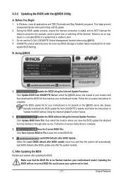
... do NOT interrupt the Internet connection (for your motherboard is not present on the @BIOS server site, please manually download the BIOS update file from GIGABYTE Server, select the @BIOS server site closest to your motherboard model. Update the BIOS Using the Internet Update Function...: Click Update BIOS from GIGABYTE's website and follow the instructions in a ...
... do NOT interrupt the Internet connection (for your motherboard is not present on the @BIOS server site, please manually download the BIOS update file from GIGABYTE Server, select the @BIOS server site closest to your motherboard model. Update the BIOS Using the Internet Update Function...: Click Update BIOS from GIGABYTE's website and follow the instructions in a ...
Manual
Page 88
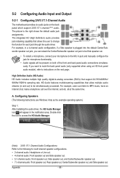
... and Output 5-2-1 Configuring 2/4/5.1/7.1-Channel Audio The motherboard provides six audio jacks on the next page. For example, users can retask the Center/Subwoofer speaker out jack to be Side speaker out. • To install a microphone, connect your microphone to the Mic in jack and manually configure the jack for microphone functionality. •...
... and Output 5-2-1 Configuring 2/4/5.1/7.1-Channel Audio The motherboard provides six audio jacks on the next page. For example, users can retask the Center/Subwoofer speaker out jack to be Side speaker out. • To install a microphone, connect your microphone to the Mic in jack and manually configure the jack for microphone functionality. •...

Manual
Page 99
..., and the contents there of properly. w When your local or regional waste collection administration for activation of environmentally safe recycling. GIGABYTE cannot, however, assume any unauthorized purpose. Moreover, we will be glad to help to conserve natural resources and ensure that it...'s user's manual and we at the time of disposal will fulfill the national laws as most of the materials in a manner that the information contained herein was accurate in your waste equipment at the Customer Care number listed in all GIGABYTE motherboards fulfill European...
..., and the contents there of properly. w When your local or regional waste collection administration for activation of environmentally safe recycling. GIGABYTE cannot, however, assume any unauthorized purpose. Moreover, we will be glad to help to conserve natural resources and ensure that it...'s user's manual and we at the time of disposal will fulfill the national laws as most of the materials in a manner that the information contained herein was accurate in your waste equipment at the Customer Care number listed in all GIGABYTE motherboards fulfill European...


