Manual
Page 35
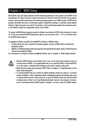
... entering the operating system. • @BIOS is turned on using the current version of BIOS, it with caution. To upgrade the BIOS, use either the GIGABYTE Q-Flash or @BIOS utility. • Q-Flash allows the user to activate certain system features. Chapter 2 BIOS Setup BIOS (Basic Input and Output System) records hardware...
... entering the operating system. • @BIOS is turned on using the current version of BIOS, it with caution. To upgrade the BIOS, use either the GIGABYTE Q-Flash or @BIOS utility. • Q-Flash allows the user to activate certain system features. Chapter 2 BIOS Setup BIOS (Basic Input and Output System) records hardware...
Manual
Page 37
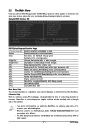
Help for each item is in the Item Help block on the right side of the submenu. • If you do not find the settings you enter the BIOS Setup program, the Main Menu (as usual, select the Load Optimized Defaults item to set your system to its defaults. • The BIOS Setup menus described in this chapter are for reference only and may differ by BIOS version. - 37 - Submenu Help While in a submenu, press to display a help screen. Use arrow keys to move among the items and press to accept or enter a sub-menu. (Sample BIOS Version: E3) CMOS Setup Utility-Copyright (C) 1984-...
Help for each item is in the Item Help block on the right side of the submenu. • If you do not find the settings you enter the BIOS Setup program, the Main Menu (as usual, select the Load Optimized Defaults item to set your system to its defaults. • The BIOS Setup menus described in this chapter are for reference only and may differ by BIOS version. - 37 - Submenu Help While in a submenu, press to display a help screen. Use arrow keys to move among the items and press to accept or enter a sub-menu. (Sample BIOS Version: E3) CMOS Setup Utility-Copyright (C) 1984-...
Manual
Page 39
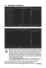
... (Note 2) Normal Normal Normal Move Enter: Select F5: Previous Values +/-/PU/PD: Value F10: Save F6: Fail-Safe Defaults ESC: Exit F1: General Help F7: Optimized Defaults CMOS Setup Utility-Copyright (C) 1984-2008 Award Software MB Intelligent Tweaker(M.I.T.) x CPU Voltage Control Normal CPU Vcore Normal... Menu Level Move Enter: Select F5: Previous Values +/-/PU/PD: Value F10: Save F6: Fail-Safe Defaults ESC: Exit F1: General Help F7: Optimized Defaults • Whether the system will work stably with the overclock/overvoltage settings you made is present only if...
... (Note 2) Normal Normal Normal Move Enter: Select F5: Previous Values +/-/PU/PD: Value F10: Save F6: Fail-Safe Defaults ESC: Exit F1: General Help F7: Optimized Defaults CMOS Setup Utility-Copyright (C) 1984-2008 Award Software MB Intelligent Tweaker(M.I.T.) x CPU Voltage Control Normal CPU Vcore Normal... Menu Level Move Enter: Select F5: Previous Values +/-/PU/PD: Value F10: Save F6: Fail-Safe Defaults ESC: Exit F1: General Help F7: Optimized Defaults • Whether the system will work stably with the overclock/overvoltage settings you made is present only if...

Manual
Page 40
... 3T 21T 3T Item Help Menu Level Move Enter: Select F5: Previous Values +/-/PU/PD: Value F10: Save F6: Fail-Safe Defaults ESC: Exit F1: General Help F7: Optimized Defaults DDRII Timing Items Manual allows all DDRII Timing items below to CAS R/W Delay Options are: Auto (default), 3T~6T. Minimum..., 195ns, 327.5ns. CAS# latency Options are : Auto (default), 75ns, 105ns, 127.5ns, 195ns, 327.5ns. Trfc0 for DIMM4 Options are : Auto (default), 3T~6T. GA-MA780G-UD3H Motherboard - 40 -
... 3T 21T 3T Item Help Menu Level Move Enter: Select F5: Previous Values +/-/PU/PD: Value F10: Save F6: Fail-Safe Defaults ESC: Exit F1: General Help F7: Optimized Defaults DDRII Timing Items Manual allows all DDRII Timing items below to CAS R/W Delay Options are: Auto (default), 3T~6T. Minimum..., 195ns, 327.5ns. CAS# latency Options are : Auto (default), 75ns, 105ns, 127.5ns, 195ns, 327.5ns. Trfc0 for DIMM4 Options are : Auto (default), 3T~6T. GA-MA780G-UD3H Motherboard - 40 -

Manual
Page 43
..., But Keyboard] Base Memory Extended Memory 640K 1790M Move Enter: Select F5: Previous Values +/-/PU/PD: Value F10: Save F6: Fail-Safe Default ESC: Exit F1: General Help F7: Optimized Defaults Date Sets the system date.
..., But Keyboard] Base Memory Extended Memory 640K 1790M Move Enter: Select F5: Previous Values +/-/PU/PD: Value F10: Save F6: Fail-Safe Default ESC: Exit F1: General Help F7: Optimized Defaults Date Sets the system date.
Manual
Page 45
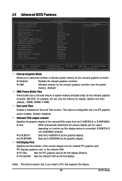
...] [Disabled] [Disabled] [Enabled] Item Help Menu Level Move Enter: Select F5: Previous Values +/-/PU/PD: Value F10: Save F6: Fail-Safe Defaults ESC: Exit F1: General Help F7: Optimized Defaults Internal Graphics Mode Allows you install a CPU that supports this memory for the onboard graphics controller . Init Display First Specifies...
...] [Disabled] [Disabled] [Enabled] Item Help Menu Level Move Enter: Select F5: Previous Values +/-/PU/PD: Value F10: Save F6: Fail-Safe Defaults ESC: Exit F1: General Help F7: Optimized Defaults Internal Graphics Mode Allows you install a CPU that supports this memory for the onboard graphics controller . Init Display First Specifies...
Manual
Page 47
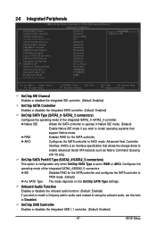
...] [378/IRQ7] [SPP] 3 Item Help Menu Level Move Enter: Select F5: Previous Values +/-/PU/PD: Value F10: Save F6: Fail-Safe Defaults ESC: Exit F1: General Help F7: Optimized Defaults OnChip IDE Channel Enables or disables the integrated IDE controller. (Default: Enabled) OnChip SATA Controller Enables or disables the integrated...
...] [378/IRQ7] [SPP] 3 Item Help Menu Level Move Enter: Select F5: Previous Values +/-/PU/PD: Value F10: Save F6: Fail-Safe Defaults ESC: Exit F1: General Help F7: Optimized Defaults OnChip IDE Channel Enables or disables the integrated IDE controller. (Default: Enabled) OnChip SATA Controller Enables or disables the integrated...
Manual
Page 48
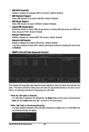
... = 0m / Length = 0m Item Help Menu Level Move Enter: Select F5: Previous Values +/-/PU/PD: Value F10: Save F6: Fail-Safe Defaults ESC: Exit F1: General Help F7: Optimized Defaults This motherboard incorporates cable diagnostic feature designed to detect the status of wires will detect cabling issue and report the... disables the onboard LAN function. (Default: Enabled) If you wish to install a 3rd party add-in the figure above. Link Detected --> 100Mbps Cable Length= 30m GA-MA780G-UD3H Motherboard - 48 -
... = 0m / Length = 0m Item Help Menu Level Move Enter: Select F5: Previous Values +/-/PU/PD: Value F10: Save F6: Fail-Safe Defaults ESC: Exit F1: General Help F7: Optimized Defaults This motherboard incorporates cable diagnostic feature designed to detect the status of wires will detect cabling issue and report the... disables the onboard LAN function. (Default: Enabled) If you wish to install a 3rd party add-in the figure above. Link Detected --> 100Mbps Cable Length= 30m GA-MA780G-UD3H Motherboard - 48 -

Manual
Page 50
... F6: Fail-Safe Defaults ESC: Exit F1: General Help F7: Optimized Defaults ACPI Suspend Type Specifies the ACPI sleep state when the system enters suspend. If the power button is pressed for 4 seconds to its working state exactly where it was left off the system. GA-MA780G-UD3H Motherboard - 50 - Delay 4 Sec. Enables the...
... F6: Fail-Safe Defaults ESC: Exit F1: General Help F7: Optimized Defaults ACPI Suspend Type Specifies the ACPI sleep state when the system enters suspend. If the power button is pressed for 4 seconds to its working state exactly where it was left off the system. GA-MA780G-UD3H Motherboard - 50 - Delay 4 Sec. Enables the...

Manual
Page 52
... F1: General Help F7: Optimized Defaults BIOS auto-assigns IRQ to the first PCI slot. (Default) Assigns IRQ 3,4,5,7,9,10,11,12,14,15 to the second PCI slot. BIOS auto-assigns IRQ to the second PCI slot. (Default) Assigns IRQ 3,4,5,7,9,10,11,12,14,15 to the first PCI slot. GA-MA780G-UD3H Motherboard...
... F1: General Help F7: Optimized Defaults BIOS auto-assigns IRQ to the first PCI slot. (Default) Assigns IRQ 3,4,5,7,9,10,11,12,14,15 to the second PCI slot. BIOS auto-assigns IRQ to the second PCI slot. (Default) Assigns IRQ 3,4,5,7,9,10,11,12,14,15 to the first PCI slot. GA-MA780G-UD3H Motherboard...
Manual
Page 53
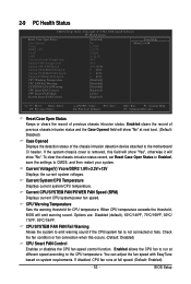
...] [Enabled] [Auto] [Enabled] Item Help Menu Level Move Enter: Select F5: Previous Values +/-/PU/PD: Value F10: Save F6: Fail-Safe Defaults ESC: Exit F1: General Help F7: Optimized Defaults Reset Case Open Status Keeps or clears the record of the chassis intrusion detection device attached to the motherboard CI...
...] [Enabled] [Auto] [Enabled] Item Help Menu Level Move Enter: Select F5: Previous Values +/-/PU/PD: Value F10: Save F6: Fail-Safe Defaults ESC: Exit F1: General Help F7: Optimized Defaults Reset Case Open Status Keeps or clears the record of the chassis intrusion detection device attached to the motherboard CI...
Manual
Page 66
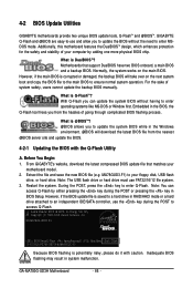
...copy the BIOS file to the main BIOS to -use and allow you can access Q-Flash by adding one more physical BIOS chip. MA78GUD3.F1) to enter Q-Flash. GA-MA780G-UD3H E3 . . . . : BIOS Setup/Q-Flash : XpressRecovery2 : Boot Menu : Qflash 12/12/2008-RS780-SB700-6A66AG0ZC-00 Because BIOS... BIOS and a backup BIOS. During the POST, press the key to your floppy disk, USB flash drive, or hard drive. GA-MA780G-UD3H Motherboard - 66 - GIGABYTE Q-Flash and @BIOS are easy-to ensure normal system operation. TM Motherboards that matches your computer by either pressing the key during ...
...copy the BIOS file to the main BIOS to -use and allow you can access Q-Flash by adding one more physical BIOS chip. MA78GUD3.F1) to enter Q-Flash. GA-MA780G-UD3H E3 . . . . : BIOS Setup/Q-Flash : XpressRecovery2 : Boot Menu : Qflash 12/12/2008-RS780-SB700-6A66AG0ZC-00 Because BIOS... BIOS and a backup BIOS. During the POST, press the key to your floppy disk, USB flash drive, or hard drive. GA-MA780G-UD3H Motherboard - 66 - GIGABYTE Q-Flash and @BIOS are easy-to ensure normal system operation. TM Motherboards that matches your computer by either pressing the key during ...

Manual
Page 76
... press to enter BIOS Setup during the POST (Power-On Self-Test). Ensure OnChip SATA Controller is enabled under Integrated Peripherals. GA-MA780G-UD3H Motherboard - 76 - CMOS Setup Utility-Copyright (C) 1984-2008 Award Software Integrated Peripherals OnChip IDE Channel OnChip SATA Controller OnChip SATA...Menu Level Move Enter: Select F5: Previous Values +/-/PU/PD: Value F10: Save F6: Fail-Safe Defaults Figure 1 ESC: Exit F1: General Help F7: Optimized Defaults Step 2: Save changes and exit BIOS Setup. To enable RAID for the SATA2_4/5 connectors, set OnChip SATA ...
... press to enter BIOS Setup during the POST (Power-On Self-Test). Ensure OnChip SATA Controller is enabled under Integrated Peripherals. GA-MA780G-UD3H Motherboard - 76 - CMOS Setup Utility-Copyright (C) 1984-2008 Award Software Integrated Peripherals OnChip IDE Channel OnChip SATA Controller OnChip SATA...Menu Level Move Enter: Select F5: Previous Values +/-/PU/PD: Value F10: Save F6: Fail-Safe Defaults Figure 1 ESC: Exit F1: General Help F7: Optimized Defaults Step 2: Save changes and exit BIOS Setup. To enable RAID for the SATA2_4/5 connectors, set OnChip SATA ...
Manual
Page 94
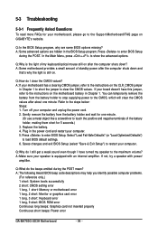
...long, 3 short: Keyboard error 1 long, 9 short: BIOS ROM error Continuous long beeps: Graphics card not inserted properly Continuous short beeps: Power error GA-MA780G-UD3H Motherboard - 94 - Q:Why is the light of my keyboard/optical mouse still on after the computer shuts down ? A: Some motherboard provides a small amount... the battery holder and wait for one minute. Turn off your motherboard has a clearing CMOS jumper, refer to the instructions on GIGABYTE's website. Gently remove the battery from the battery holder to stop supplying power to the CMOS, which will clear the CMOS values...
...long, 3 short: Keyboard error 1 long, 9 short: BIOS ROM error Continuous long beeps: Graphics card not inserted properly Continuous short beeps: Power error GA-MA780G-UD3H Motherboard - 94 - Q:Why is the light of my keyboard/optical mouse still on after the computer shuts down ? A: Some motherboard provides a small amount... the battery holder and wait for one minute. Turn off your motherboard has a clearing CMOS jumper, refer to the instructions on GIGABYTE's website. Gently remove the battery from the battery holder to stop supplying power to the CMOS, which will clear the CMOS values...