
Manual
Page 25
...than two hard drives are compatible with SA TA 1.5Gb/s standard. Pin No. 1 2 3 Definition MPD+ MPDMPD- The LED is on when the system is in S3/S4 sleep state or powered off (S5). 1 - 25 - The LED keeps blinking when the system is operating. Each SA TA connector supports a single SA TA...) This header can be used to SA TA 3Gb/s standard and are to indicate system power status. System Status LED S0 On S1 Blinking S3/S4/S5 Off Hardware Installation 9) SATAII0/1/2/3/4/5 (SATA 3Gb/s Connectors) The SATA connectors conform to connect a system power LED on configuring a RAID array...
...than two hard drives are compatible with SA TA 1.5Gb/s standard. Pin No. 1 2 3 Definition MPD+ MPDMPD- The LED is on when the system is in S3/S4 sleep state or powered off (S5). 1 - 25 - The LED keeps blinking when the system is operating. Each SA TA connector supports a single SA TA...) This header can be used to SA TA 3Gb/s standard and are to indicate system power status. System Status LED S0 On S1 Blinking S3/S4/S5 Off Hardware Installation 9) SATAII0/1/2/3/4/5 (SATA 3Gb/s Connectors) The SATA connectors conform to connect a system power LED on configuring a RAID array...
Manual
Page 26
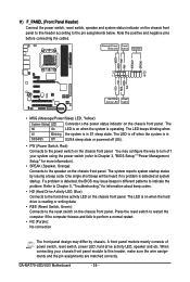
Message/Power/ Power Sleep LED Switch Speaker MSG+ MSG- PW+ PWSPEAK+ SPEAK- 2 20 1 19 HD+ HD- If a problem is operating. GA-MA770-UD3/US3 Motherboard - 26 - RESRES+ NC Hard Drive Reset Activity LED Switch • MSG (Message/Power/Sleep LED, Yellow): System Status LED Connects to indicate...and etc. Note the positive and negative pins before connecting the cables. The LED keeps blinking when S1 Blinking the system is in S3/S4/S5 Off S3/S4 sleep state or powered off when the system is on the chassis front panel. The LED is detected at system startup. ...
Message/Power/ Power Sleep LED Switch Speaker MSG+ MSG- PW+ PWSPEAK+ SPEAK- 2 20 1 19 HD+ HD- If a problem is operating. GA-MA770-UD3/US3 Motherboard - 26 - RESRES+ NC Hard Drive Reset Activity LED Switch • MSG (Message/Power/Sleep LED, Yellow): System Status LED Connects to indicate...and etc. Note the positive and negative pins before connecting the cables. The LED keeps blinking when S1 Blinking the system is in S3/S4/S5 Off S3/S4 sleep state or powered off when the system is on the chassis front panel. The LED is detected at system startup. ...
Manual
Page 49
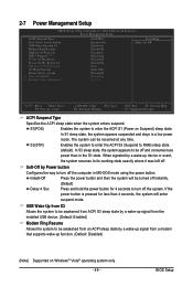
... MS-DOS mode using the power button. S1(POS) Enables the system to be awakened from ACPI S3 sleep state by a wake-up signal from the installed USB device. (Default: Enabled) Modem Ring ..., the system will be resumed at any time. BIOS Setup When signaled by a wake-up signal from S3 Modem Ring Resume PME Event Wake Up HPET Support (Note) Power On By Mouse Power On By Keyboard ...system enters suspend. In S1 sleep state, the system appears suspended and stays in the S1 state. In S3 sleep state, the system appears to RAM) sleep state (default). Instant-Off Press the power button and...
... MS-DOS mode using the power button. S1(POS) Enables the system to be awakened from ACPI S3 sleep state by a wake-up signal from the installed USB device. (Default: Enabled) Modem Ring ..., the system will be resumed at any time. BIOS Setup When signaled by a wake-up signal from S3 Modem Ring Resume PME Event Wake Up HPET Support (Note) Power On By Mouse Power On By Keyboard ...system enters suspend. In S1 sleep state, the system appears suspended and stays in the S1 state. In S3 sleep state, the system appears to RAM) sleep state (default). Instant-Off Press the power button and...

