Manual
Page 1
GA-M720-US3 AM2+/AM2 socket motherboard for AMD PhenomTM FX processor/AMD PhenomTM X4 processor/ AMD PhenomTM X3 processor/AMD AthlonTM X2 processor/ AMD AthlonTM processor/AMD SempronTM X2 processor/ AMD SempronTM processor User's Manual Rev. 1002 12ME-M720US3-1002R
GA-M720-US3 AM2+/AM2 socket motherboard for AMD PhenomTM FX processor/AMD PhenomTM X4 processor/ AMD PhenomTM X3 processor/AMD AthlonTM X2 processor/ AMD AthlonTM processor/AMD SempronTM X2 processor/ AMD SempronTM processor User's Manual Rev. 1002 12ME-M720US3-1002R
Manual
Page 2
Motherboard GA-M720-US3 Dec. 8, 2008 Motherboard GA-M720-US3 Dec. 8, 2008
Motherboard GA-M720-US3 Dec. 8, 2008 Motherboard GA-M720-US3 Dec. 8, 2008
Manual
Page 4
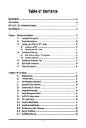
Table of Contents Box Contents ...6 OptionalItems...6 GA-M720-US3 Motherboard Layout 7 Block Diagram...8 Chapter 1 Hardware Installation 9 1-1 Installation Precautions 9 1-2 Product Specifications 10 1-3 Installing the CPU and CPU Cooler 12 1-3-1 Installing the CPU 12 1-3-2 Installing the ...
Table of Contents Box Contents ...6 OptionalItems...6 GA-M720-US3 Motherboard Layout 7 Block Diagram...8 Chapter 1 Hardware Installation 9 1-1 Installation Precautions 9 1-2 Product Specifications 10 1-3 Installing the CPU and CPU Cooler 12 1-3-1 Installing the CPU 12 1-3-2 Installing the ...
Manual
Page 6
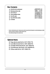
Box Contents GA-M720-US3 motherboard Motherboard driver disk User's Manual Quick Installation Guide One IDE cable Two SATA 3Gb/s cables I/O Shield • The box contents above are subject to ...
Box Contents GA-M720-US3 motherboard Motherboard driver disk User's Manual Quick Installation Guide One IDE cable Two SATA 3Gb/s cables I/O Shield • The box contents above are subject to ...
Manual
Page 10
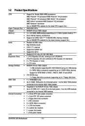
...processor/AMD AthlonTM X2 processor/ AMD AthlonTM processor/AMD SempronTM X2 processor/ AMD SempronTM processor (Go to GIGABYTE's website for the latest CPU support list.) 5200/2000 MT/s NVIDIA® nForce 720D chipset 4 x...Note 1) Dual channel memory architecture Support for DDR2 1200 (Note 2)/1066/800 MHz memory modules (Go to GIGABYTE's website for the latest memory support list.) Realtek ALC888 codec High Definition Audio 2/4/5.1/7.1-channel Support for S/PDIF ...connectors 1 x CPU fan header 2 x system fan headers 1 x power fan header 1 x front panel header GA-M720-US3 Motherboard - 10 -
...processor/AMD AthlonTM X2 processor/ AMD AthlonTM processor/AMD SempronTM X2 processor/ AMD SempronTM processor (Go to GIGABYTE's website for the latest CPU support list.) 5200/2000 MT/s NVIDIA® nForce 720D chipset 4 x...Note 1) Dual channel memory architecture Support for DDR2 1200 (Note 2)/1066/800 MHz memory modules (Go to GIGABYTE's website for the latest memory support list.) Realtek ALC888 codec High Definition Audio 2/4/5.1/7.1-channel Support for S/PDIF ...connectors 1 x CPU fan header 2 x system fan headers 1 x power fan header 1 x front panel header GA-M720-US3 Motherboard - 10 -
Manual
Page 12
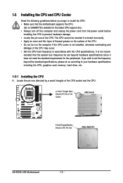
... and unplug the power cord from the power outlet before you wish to set beyond the standard specifications, please do so according to GIGABYTE's website for the peripherals. Locate the pin one of the CPU. A Small Triangle Mark Denotes Pin One of the CPU socket and... • Locate the pin one (denoted by a small triangle) of the Socket AM2 Socket A Small Triangle Marking Denotes CPU Pin One AM2+/AM2 CPU GA-M720-US3 Motherboard - 12 - mended that the motherboard supports the CPU. (Go to your hardware specifications including the CPU, graphics card, memory, hard drive, etc...
... and unplug the power cord from the power outlet before you wish to set beyond the standard specifications, please do so according to GIGABYTE's website for the peripherals. Locate the pin one of the CPU. A Small Triangle Mark Denotes Pin One of the CPU socket and... • Locate the pin one (denoted by a small triangle) of the Socket AM2 Socket A Small Triangle Marking Denotes CPU Pin One AM2+/AM2 CPU GA-M720-US3 Motherboard - 12 - mended that the motherboard supports the CPU. (Go to your hardware specifications including the CPU, graphics card, memory, hard drive, etc...
Manual
Page 14
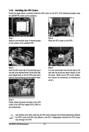
1-3-2 Installing the CPU Cooler Follow the steps below to correctly install the CPU cooler on the CPU. (The following procedure uses the GIGABYTE cooler as the picture above shows) to lock into place. (Refer to your CPU cooler installation manual for instructions on installing the cooler.)...lug on the motherboard. Inadequately removing the CPU cooler may adhere to the CPU fan header (CPU_FAN) on one side of the retention frame. GA-M720-US3 Motherboard - 14 - Step 2: Place the CPU cooler on the retention frame. Use extreme care when removing the CPU cooler because the thermal ...
1-3-2 Installing the CPU Cooler Follow the steps below to correctly install the CPU cooler on the CPU. (The following procedure uses the GIGABYTE cooler as the picture above shows) to lock into place. (Refer to your CPU cooler installation manual for instructions on installing the cooler.)...lug on the motherboard. Inadequately removing the CPU cooler may adhere to the CPU fan header (CPU_FAN) on one side of the retention frame. GA-M720-US3 Motherboard - 14 - Step 2: Place the CPU cooler on the retention frame. Use extreme care when removing the CPU cooler because the thermal ...
Manual
Page 16
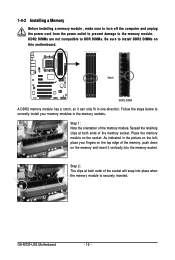
... fit in the memory sockets. Notch DDR2 DIMM A DDR2 memory module has a notch, so it vertically into place when the memory module is securely inserted. GA-M720-US3 Motherboard - 16 - Step 1: Note the orientation of the socket will snap into the memory socket. As indicated in the picture on the left, place your...
... fit in the memory sockets. Notch DDR2 DIMM A DDR2 memory module has a notch, so it vertically into place when the memory module is securely inserted. GA-M720-US3 Motherboard - 16 - Step 1: Note the orientation of the socket will snap into the memory socket. As indicated in the picture on the left, place your...
Manual
Page 18
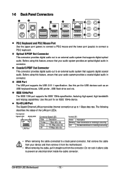
... connector. Do not rock it straight out from the connector. Before using this feature, ensure that your audio system provides a coaxial digital audio in connector. GA-M720-US3 Motherboard - 18 - Coaxial S/PDIF Out Connector This connector provides digital audio out to 1 Gbps data rate. RJ-45 LAN Port The Gigabit Ethernet LAN port...
... connector. Do not rock it straight out from the connector. Before using this feature, ensure that your audio system provides a coaxial digital audio in connector. GA-M720-US3 Motherboard - 18 - Coaxial S/PDIF Out Connector This connector provides digital audio out to 1 Gbps data rate. RJ-45 LAN Port The Gigabit Ethernet LAN port...
Manual
Page 20
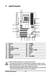
... sure your devices are compliant with the connectors you wish to connect. • Before installing the devices, be sure to the connector on the motherboard. GA-M720-US3 Motherboard - 20 - Unplug the power cord from the power outlet to prevent damage to the devices. • After installing the device and before connecting external...
... sure your devices are compliant with the connectors you wish to connect. • Before installing the devices, be sure to the connector on the motherboard. GA-M720-US3 Motherboard - 20 - Unplug the power cord from the power outlet to prevent damage to the devices. • After installing the device and before connecting external...
Manual
Page 22
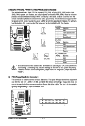
The pin 1 of the cable is used to locate pin 1 of different color. 33 1 34 2 GA-M720-US3 Motherboard - 22 - Overheating may hang. • These fan headers are : 360 KB, 720 KB, 1.2 MB, 1.44 MB, and 2.88 MB. Do not place a jumper cap ...
The pin 1 of the cable is used to locate pin 1 of different color. 33 1 34 2 GA-M720-US3 Motherboard - 22 - Overheating may hang. • These fan headers are : 360 KB, 720 KB, 1.2 MB, 1.44 MB, and 2.88 MB. Do not place a jumper cap ...
Manual
Page 24
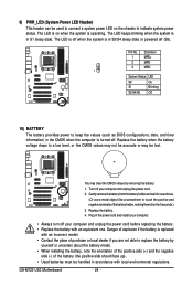
.... You may be used to connect a system power LED on when the system is turned off. Turn off your computer and unplug the power cord. 2. GA-M720-US3 Motherboard - 24 - The LED keeps blinking when the system is in S3/S4 sleep state or powered off when the system is in the power...
.... You may be used to connect a system power LED on when the system is turned off. Turn off your computer and unplug the power cord. 2. GA-M720-US3 Motherboard - 24 - The LED keeps blinking when the system is in S3/S4 sleep state or powered off when the system is in the power...
Manual
Page 26
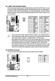
... assignments, please contact the chassis manufacturer. 13) CD_IN (CD In Connector) You may connect your optical drive to this header. Definition 1 CD-L 1 2 GND 3 GND 4 CD-R GA-M720-US3 Motherboard - 26 - You may connect the audio cable that has separated connectors on each wire instead of a single plug. Pin No. Incorrect connection between the...
... assignments, please contact the chassis manufacturer. 13) CD_IN (CD In Connector) You may connect your optical drive to this header. Definition 1 CD-L 1 2 GND 3 GND 4 CD-R GA-M720-US3 Motherboard - 26 - You may connect the audio cable that has separated connectors on each wire instead of a single plug. Pin No. Incorrect connection between the...
Manual
Page 28
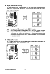
... optional COM port cable, please contact the local dealer. 9 1 10 2 Pin No. 1 2 3 4 5 6 7 8 9 10 Definition NDCD NSIN NSOUT NDTR GND NDSR NRTS NCTS NRI No Pin GA-M720-US3 Motherboard - 28 - The IEEE 1394a header can provide one end of the device cable to your computer and unplug the power cord from the power...
... optional COM port cable, please contact the local dealer. 9 1 10 2 Pin No. 1 2 3 4 5 6 7 8 9 10 Definition NDCD NSIN NSOUT NDTR GND NDSR NRTS NCTS NRI No Pin GA-M720-US3 Motherboard - 28 - The IEEE 1394a header can provide one end of the device cable to your computer and unplug the power cord from the power...
Manual
Page 32
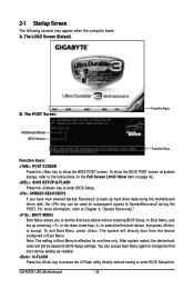
...Boot Menu. 2-1 Startup Screen The following screens may appear when the computer boots. The LOGO Screen (Default) B. To exit Boot Menu, press . GA-M720-US3 Motherboard - 32 - You can be based on page 42. : BIOS SETUP\Q-FLASH Press the key to enter BIOS Setup. : XPRESS RECOVERY2 If ...you to set the first boot device without having to access the Q-Flash utility directly without entering BIOS Setup. To show the BIOS POST screen. A. M720-US3 F1ec . . . . : BIOS Setup : XpressRecovery2 : Boot Menu : Qflash 12/26/2008-NF-MCP78-6A610G06C-00 Function Keys Function Keys Function Keys...
...Boot Menu. 2-1 Startup Screen The following screens may appear when the computer boots. The LOGO Screen (Default) B. To exit Boot Menu, press . GA-M720-US3 Motherboard - 32 - You can be based on page 42. : BIOS SETUP\Q-FLASH Press the key to enter BIOS Setup. : XPRESS RECOVERY2 If ...you to set the first boot device without having to access the Q-Flash utility directly without entering BIOS Setup. To show the BIOS POST screen. A. M720-US3 F1ec . . . . : BIOS Setup : XpressRecovery2 : Boot Menu : Qflash 12/26/2008-NF-MCP78-6A610G06C-00 Function Keys Function Keys Function Keys...
Manual
Page 34
... This function allows you to save the current BIOS settings to the confirmation message will exit BIOS Setup. (Pressing can also carry out this task.) GA-M720-US3 Motherboard - 34 - Pressing to a profile. A supervisor password allows you to make changes. Save & Exit Setup Save all the changes made in the BIOS Setup...
... This function allows you to save the current BIOS settings to the confirmation message will exit BIOS Setup. (Pressing can also carry out this task.) GA-M720-US3 Motherboard - 34 - Pressing to a profile. A supervisor password allows you to make changes. Save & Exit Setup Save all the changes made in the BIOS Setup...
Manual
Page 36
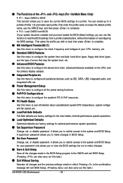
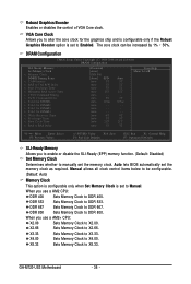
... Set Memory Clock is set the memory clock as required. DDR 667 Sets Memory Clock to X4.00. X3.33 Sets Memory Clock to Manual. GA-M720-US3 Motherboard - 36 - Robust Graphics Booster Enables or disables the control of VGA Core clock. Manual allows all clock control items below to be increased by...
... Set Memory Clock is set the memory clock as required. DDR 667 Sets Memory Clock to X4.00. X3.33 Sets Memory Clock to Manual. GA-M720-US3 Motherboard - 36 - Robust Graphics Booster Enables or disables the control of VGA Core clock. Manual allows all clock control items below to be increased by...
Manual
Page 38
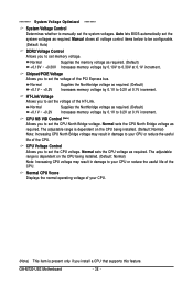
.... (Default) +0.1V ~ +0.2V Increases memory voltage by 0.1V to set the voltage of the CPU. CPU Voltage Control Allows you to 0.2V at 0.1V increment. GA-M720-US3 Motherboard - 38 - ******** System Voltage Optimized ******** System Voltage Control Determines whether to set the CPU voltage. Normal Supplies the Northbridge voltage as required. (Default) +0.10V ~ +0.30V...
.... (Default) +0.1V ~ +0.2V Increases memory voltage by 0.1V to set the voltage of the CPU. CPU Voltage Control Allows you to 0.2V at 0.1V increment. GA-M720-US3 Motherboard - 38 - ******** System Voltage Optimized ******** System Voltage Control Determines whether to set the CPU voltage. Normal Supplies the Northbridge voltage as required. (Default) +0.10V ~ +0.30V...
Manual
Page 40
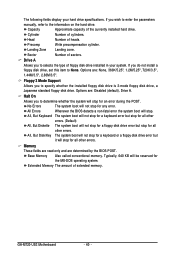
... for a keyboard error but stop for all other errors. (Default) All, But Diskette The system boot will not stop for an error during the POST. GA-M720-US3 Motherboard - 40 - If you to specify whether the installed floppy disk drive is 3-mode floppy disk drive, a Japanese standard floppy disk drive. Floppy 3 Mode Support...
... for a keyboard error but stop for all other errors. (Default) All, But Diskette The system boot will not stop for an error during the POST. GA-M720-US3 Motherboard - 40 - If you to specify whether the installed floppy disk drive is 3-mode floppy disk drive, a Japanese standard floppy disk drive. Floppy 3 Mode Support...
Manual
Page 42
... initiation of your system to report read/write errors of the hard drive and to display the GIGABYTE Logo at system startup. PCI Slot Sets the PCI graphics card as the first display. (Default) GA-M720-US3 Motherboard - 42 - After configuring this item, set the password(s) under the Set Supervisor/User Password item in...
... initiation of your system to report read/write errors of the hard drive and to display the GIGABYTE Logo at system startup. PCI Slot Sets the PCI graphics card as the first display. (Default) GA-M720-US3 Motherboard - 42 - After configuring this item, set the password(s) under the Set Supervisor/User Password item in...
