
Manual
Page 3
...protected by GIGA-BYTE TECHNOLOGY CO., LTD as the exclu- Example: sive global distributor of GIGABYTE. Disclaimer Information in any form or by any means without prior notice. Documentation Classifications In order to assist in the...For instructions on your motherboard revision before updating motherboard BIOS, drivers, or when looking for technical information. GIGABYTE UNITED INC. The logo is the property of GIGABYTE branded motherboards. Changes to GIGABYTE UNITED INC. by GIGABYTE without GIGABYTE's prior written permission. For product-related information, check...
...protected by GIGA-BYTE TECHNOLOGY CO., LTD as the exclu- Example: sive global distributor of GIGABYTE. Disclaimer Information in any form or by any means without prior notice. Documentation Classifications In order to assist in the...For instructions on your motherboard revision before updating motherboard BIOS, drivers, or when looking for technical information. GIGABYTE UNITED INC. The logo is the property of GIGABYTE branded motherboards. Changes to GIGABYTE UNITED INC. by GIGABYTE without GIGABYTE's prior written permission. For product-related information, check...
Manual
Page 4
Table of Contents OptionalItems ...6 Box Contents ...6 GA-M61SME-S2L Motherboard Layout 7 Block Diagram ...8 Chapter 1 Hardware Installation 9 1-1 Installation Precautions 9 1-2 Product Specifications 10 1-3 Installing the CPU and CPU Cooler 12... Memory 16 1-5 Installing an Expansion Card 17 1-6 Back Panel Connectors 20 1-7 Internal Connectors 22 Chapter 2 BIOS Setup 31 2-1 Startup Screen 32 2-2 The Main Menu 33 2-3 Standard CMOS Features 35 2-4 Advanced BIOS Features 37 2-5 IntegratedPeripherals 39 2-6 Power Management Setup 42 2-7 PnP/PCI Configurations 44 2-8 PC Health Status...
Table of Contents OptionalItems ...6 Box Contents ...6 GA-M61SME-S2L Motherboard Layout 7 Block Diagram ...8 Chapter 1 Hardware Installation 9 1-1 Installation Precautions 9 1-2 Product Specifications 10 1-3 Installing the CPU and CPU Cooler 12... Memory 16 1-5 Installing an Expansion Card 17 1-6 Back Panel Connectors 20 1-7 Internal Connectors 22 Chapter 2 BIOS Setup 31 2-1 Startup Screen 32 2-2 The Main Menu 33 2-3 Standard CMOS Features 35 2-4 Advanced BIOS Features 37 2-5 IntegratedPeripherals 39 2-6 Power Management Setup 42 2-7 PnP/PCI Configurations 44 2-8 PC Health Status...

Manual
Page 5
... 52 3-3 Driver CD Information 52 3-4 Hardware Information 53 3-5 Contact Us ...53 Chapter 4 Unique Features 55 4-1 Xpress Recovery2 55 4-2 BIOS Update Utilities 60 4-2-1 Updating the BIOS with the Q-Flash Utility 60 4-2-2 Updating the BIOS with the @BIOS Utility 63 4-3 EasyTune 5 ...65 4-4 Windows Vista ReadyBoost 66 Chapter 5 Appendix ...67 5-1 Configuring SATA Hard Drive(s 67 5-1-1 Configuring the...
... 52 3-3 Driver CD Information 52 3-4 Hardware Information 53 3-5 Contact Us ...53 Chapter 4 Unique Features 55 4-1 Xpress Recovery2 55 4-2 BIOS Update Utilities 60 4-2-1 Updating the BIOS with the Q-Flash Utility 60 4-2-2 Updating the BIOS with the @BIOS Utility 63 4-3 EasyTune 5 ...65 4-4 Windows Vista ReadyBoost 66 Chapter 5 Appendix ...67 5-1 Configuring SATA Hard Drive(s 67 5-1-1 Configuring the...

Manual
Page 8
Block Diagram PCIe CLK (100 MHz) AMD Socket AM2 CPU CPU CLK+/-(200 MHz) DDR2 800/667/533 MHz DIMM Dual Channel Memory Hyper Transport Bus PCI Express x8 PCI Express x1 Bus x1 PCIe CLK (100 MHz) 1 PCI Express x1 LAN RJ45 Realtek 8201CL PCI Bus D-Sub nVIDIA® GeForce 6100/ nForce 405 8 USB Ports 2 SATA 3Gb/s ATA-133/100/66/33 IDE Channel CODEC LPC BUS IT8716 BIOS Floppy LPT Port COM Port 2 PCI PS/2 KB/Mouse MIC (Center/Subwoofer Speaker Out) Line-Out (Front Speaker Out) Line-In (Rear Speaker Out) SPDIF Out PCI CLK (33 MHz) - 8 -
Block Diagram PCIe CLK (100 MHz) AMD Socket AM2 CPU CPU CLK+/-(200 MHz) DDR2 800/667/533 MHz DIMM Dual Channel Memory Hyper Transport Bus PCI Express x8 PCI Express x1 Bus x1 PCIe CLK (100 MHz) 1 PCI Express x1 LAN RJ45 Realtek 8201CL PCI Bus D-Sub nVIDIA® GeForce 6100/ nForce 405 8 USB Ports 2 SATA 3Gb/s ATA-133/100/66/33 IDE Channel CODEC LPC BUS IT8716 BIOS Floppy LPT Port COM Port 2 PCI PS/2 KB/Mouse MIC (Center/Subwoofer Speaker Out) Line-Out (Front Speaker Out) Line-In (Rear Speaker Out) SPDIF Out PCI CLK (33 MHz) - 8 -
Manual
Page 11
...; Support for Q-Flash Š Support for EasyTune (Note 4) Š Support for Xpress Install Š Support for Xpress Recovery2 Š Support for Virtual Dual BIOS Š Norton Internet Security (OEM version) Š Support for Microsoft® Windows® Vista/XP/2000 Š Micro ATX form factor; 24.4cm x 22... limitation, when more than 4 GB of physical memory is installed, the actual memory size displayed will be less than 4 GB. (Note 2) The GA-M61SME-S2L supports up to PCI Express x8 mode. (Please refer to the graphics cards support list on page 18) (Note 3) Whether the CPU fan speed ...
...; Support for Q-Flash Š Support for EasyTune (Note 4) Š Support for Xpress Install Š Support for Xpress Recovery2 Š Support for Virtual Dual BIOS Š Norton Internet Security (OEM version) Š Support for Microsoft® Windows® Vista/XP/2000 Š Micro ATX form factor; 24.4cm x 22... limitation, when more than 4 GB of physical memory is installed, the actual memory size displayed will be less than 4 GB. (Note 2) The GA-M61SME-S2L supports up to PCI Express x8 mode. (Please refer to the graphics cards support list on page 18) (Note 3) Whether the CPU fan speed ...

Manual
Page 15
... and chips be installed in Dual Channel mode. 1. After the memory is installed. 2. Dual Channel mode cannot be used . (Go to GIGABYTE's website for the latest memory support list.) • Always turn off the computer and unplug the power cord from the power outlet before installing...direction. 1-4 Installing the Memory Read the following guidelines before installing the memory in only one DDR2 memory module is installed, the BIOS will double the original memory bandwidth. When enabling Dual Channel mode with two memory modules, it is recommended that the motherboard supports the...
... and chips be installed in Dual Channel mode. 1. After the memory is installed. 2. Dual Channel mode cannot be used . (Go to GIGABYTE's website for the latest memory support list.) • Always turn off the computer and unplug the power cord from the power outlet before installing...direction. 1-4 Installing the Memory Read the following guidelines before installing the memory in only one DDR2 memory module is installed, the BIOS will double the original memory bandwidth. When enabling Dual Channel mode with two memory modules, it is recommended that the motherboard supports the...

Manual
Page 17
.... Secure the card's metal bracket to the chassis back panel with the expansion card in the expansion slot. 1. If necessary, go to BIOS Setup to make any required BIOS changes for your computer. Hardware Installation Turn on your expansion card(s). 7. Remove the metal slot cover from the power outlet before you begin...
.... Secure the card's metal bracket to the chassis back panel with the expansion card in the expansion slot. 1. If necessary, go to BIOS Setup to make any required BIOS changes for your computer. Hardware Installation Turn on your expansion card(s). 7. Remove the metal slot cover from the power outlet before you begin...

Manual
Page 26
...(S5). System Status LED S0 On S1 Blinking S3/S4/S5 Off 9) BATTERY The battery provides power to keep the values (such as BIOS configurations, date, and time information) in the CMOS when the computer is replaced with local environmental regulations. Replace the battery when the battery ... the battery: 1. Gently remove the battery from the battery holder and wait for 5 seconds.) 3. Replace the battery. 4. Definition 1 MPD+ 2 MPD- 1 3 MPD- GA-M61SME-S2L Motherboard - 26 - The LED is on the chassis to a low level, or the CMOS values may not be lost.
...(S5). System Status LED S0 On S1 Blinking S3/S4/S5 Off 9) BATTERY The battery provides power to keep the values (such as BIOS configurations, date, and time information) in the CMOS when the computer is replaced with local environmental regulations. Replace the battery when the battery ... the battery: 1. Gently remove the battery from the battery holder and wait for 5 seconds.) 3. Replace the battery. 4. Definition 1 MPD+ 2 MPD- 1 3 MPD- GA-M61SME-S2L Motherboard - 26 - The LED is on the chassis to a low level, or the CMOS values may not be lost.

Manual
Page 27
... to the reset switch on when the system is on the chassis front panel. When connecting your system using the power switch (refer to Chapter 2, "BIOS Setup," "Power Management Setup," for information about beep codes. • HD (IDE Hard Drive Activity LED) Connects to this header, make sure the wire assignments... front panel module to this header according to indicate the problem. You may configure the way to turn off when the system is detected, the BIOS may differ by issuing a beep code.
... to the reset switch on when the system is on the chassis front panel. When connecting your system using the power switch (refer to Chapter 2, "BIOS Setup," "Power Management Setup," for information about beep codes. • HD (IDE Hard Drive Activity LED) Connects to this header, make sure the wire assignments... front panel module to this header according to indicate the problem. You may configure the way to turn off when the system is detected, the BIOS may differ by issuing a beep code.

Manual
Page 30
... use a metal object like a screwdriver to touch the two pins for BIOS configurations). Pin No. date information and BIOS configurations) and reset the CMOS values to clear the CMOS values (e.g. GA-M61SME-S2L Motherboard - 30 - Open: Normal Short: Clear CMOS Values • Always... turn off your computer, be sure to Chapter 2, "BIOS Setup," for a few seconds. This function requires a chassis with chassis intrusion detection design. Definition...
... use a metal object like a screwdriver to touch the two pins for BIOS configurations). Pin No. date information and BIOS configurations) and reset the CMOS values to clear the CMOS values (e.g. GA-M61SME-S2L Motherboard - 30 - Open: Normal Short: Clear CMOS Values • Always... turn off your computer, be sure to Chapter 2, "BIOS Setup," for a few seconds. This function requires a chassis with chassis intrusion detection design. Definition...

Manual
Page 31
...the default settings (unless you need to) to Chapter 4, "BIOS Update Utilities." • Because BIOS flashing is turned on using the current version of BIOS, it with caution. To upgrade the BIOS, use either the GIGABYTE Q-Flash or @BIOS utility. • Q-Flash allows the user to activate certain... system features. To flash the BIOS, do not encounter problems using the Q-Flash and @BIOS utilities, refer to prevent...
...the default settings (unless you need to) to Chapter 4, "BIOS Update Utilities." • Because BIOS flashing is turned on using the current version of BIOS, it with caution. To upgrade the BIOS, use either the GIGABYTE Q-Flash or @BIOS utility. • Q-Flash allows the user to activate certain... system features. To flash the BIOS, do not encounter problems using the Q-Flash and @BIOS utilities, refer to prevent...
Manual
Page 32
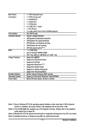
...first boot device, then press to XpressRecovery2 during the POST. 2-1 Startup Screen The following screen may appear when the computer boots. M61SME-S2L E2 . . . . : BIOS Setup/Q-Flash : XpressRecovery2 : Boot Menu : Qflash 07/10/2007-NV-MCP61-6A61KG08C-00 Function Keys Function Keys... . In Boot Menu, use the up hard drive data using the motherboard driver disk, the key can be based on BIOS Setup settings. GA-M61SME-S2L Motherboard - 32 - Motherboard Model BIOS Version Award Modular BIOS v6.00PG, An Energy Star Ally Copyright (C) 1984-2007, Award Software, Inc. Note: The setting in...
...first boot device, then press to XpressRecovery2 during the POST. 2-1 Startup Screen The following screen may appear when the computer boots. M61SME-S2L E2 . . . . : BIOS Setup/Q-Flash : XpressRecovery2 : Boot Menu : Qflash 07/10/2007-NV-MCP61-6A61KG08C-00 Function Keys Function Keys... . In Boot Menu, use the up hard drive data using the motherboard driver disk, the key can be based on BIOS Setup settings. GA-M61SME-S2L Motherboard - 32 - Motherboard Model BIOS Version Award Modular BIOS v6.00PG, An Energy Star Ally Copyright (C) 1984-2007, Award Software, Inc. Note: The setting in...

Manual
Page 33
... item is in the Item Help block on the right side of the submenu. • If you do not find the settings you enter the BIOS Setup program, the Main Menu (as usual, select the Load Optimized Defaults item to set your system to exit the help screen (General Help) of... function keys available for reference only and may differ by BIOS version. - 33 - Press to its defaults. • The BIOS Setup menus described in the Main Menu or a submenu, press + to access more advanced options. • When the system is displayed...
... item is in the Item Help block on the right side of the submenu. • If you do not find the settings you enter the BIOS Setup program, the Main Menu (as usual, select the Load Optimized Defaults item to set your system to exit the help screen (General Help) of... function keys available for reference only and may differ by BIOS version. - 33 - Press to its defaults. • The BIOS Setup menus described in the Main Menu or a submenu, press + to access more advanced options. • When the system is displayed...

Manual
Page 34
...task.) „ Exit Without Saving Abandon all changes and the previous settings remain in the BIOS Setup program to the CMOS and exit BIOS Setup. (Pressing can also carry out this menu to see information about autodetected system/CPU temperature... types, floppy disk drive types, and the type of errors that stop the system boot, etc. „ Advanced BIOS Features Use this menu to configure the device boot order, advanced features available on the CPU, and the primary display...configure the system's PCI & PnP resources. „ PC Health Status Use this task.) GA-M61SME-S2L Motherboard - 34 -
...task.) „ Exit Without Saving Abandon all changes and the previous settings remain in the BIOS Setup program to the CMOS and exit BIOS Setup. (Pressing can also carry out this menu to see information about autodetected system/CPU temperature... types, floppy disk drive types, and the type of errors that stop the system boot, etc. „ Advanced BIOS Features Use this menu to configure the device boot order, advanced features available on the CPU, and the primary display...configure the system's PCI & PnP resources. „ PC Health Status Use this task.) GA-M61SME-S2L Motherboard - 34 -

Manual
Page 35
...the hard drive access mode. IDE Channel 2/3 Master IDE Auto-Detection Press to autodetect the parameters of the IDE/SATA device on this channel. BIOS Setup IDE Channel 0 Master/Slave IDE HDD Auto-Detection Press to autodetect the parameters of the IDE/SATA device on this channel. Options are...item to CHS. IDE Channel 0 Master/Slave Configure your IDE/SATA devices by using one of the three methods below : • Auto Lets BIOS automatically detect IDE/SATA devices during the POST. (Default) • None If no IDE/SATA devices are used , set this item to None...
...the hard drive access mode. IDE Channel 2/3 Master IDE Auto-Detection Press to autodetect the parameters of the IDE/SATA device on this channel. BIOS Setup IDE Channel 0 Master/Slave IDE HDD Auto-Detection Press to autodetect the parameters of the IDE/SATA device on this channel. Options are...item to CHS. IDE Channel 0 Master/Slave Configure your IDE/SATA devices by using one of the three methods below : • Auto Lets BIOS automatically detect IDE/SATA devices during the POST. (Default) • None If no IDE/SATA devices are used , set this item to None...

Manual
Page 36
... : Disabled (default), Drive A. All Errors Whenever the BIOS detects a non-fatal error the system boot will stop for the MS-DOS operating system. All, But Disk/Key The system boot will be reserved for all other errors. Memory These fields are read-only and are determined by the BIOS POST. GA-M61SME-S2L Motherboard - 36 -
... : Disabled (default), Drive A. All Errors Whenever the BIOS detects a non-fatal error the system boot will stop for the MS-DOS operating system. All, But Disk/Key The system boot will be reserved for all other errors. Memory These fields are read-only and are determined by the BIOS POST. GA-M61SME-S2L Motherboard - 36 -

Manual
Page 37
... to move it up or down on the list. Password Check Specifies whether a password is required for booting the system and for entering the BIOS Setup program. Capability Enables or disables the S.M.A.R.T. (Self Monitoring and Reporting Technology) capability of loading the operating system from the installed hard drives... of the hard drive and to accept. After configuring this item, set the password(s) under the Set Supervisor/User Password item in the BIOS Main Menu. Use the up or down arrow key to select a device and press to issue warnings when a third party hardware monitor...
... to move it up or down on the list. Password Check Specifies whether a password is required for booting the system and for entering the BIOS Setup program. Capability Enables or disables the S.M.A.R.T. (Self Monitoring and Reporting Technology) capability of loading the operating system from the installed hard drives... of the hard drive and to accept. After configuring this item, set the password(s) under the Set Supervisor/User Password item in the BIOS Main Menu. Use the up or down arrow key to select a device and press to issue warnings when a third party hardware monitor...

Manual
Page 39
...` KLJI: Move Enter: Select F5: Previous Values +/-/PU/PD: Value F10: Save F6: Fail-Safe Defaults ESC: Exit F1: General Help F7: Optimized Defaults - 39 - BIOS Setup
...` KLJI: Move Enter: Select F5: Previous Values +/-/PU/PD: Value F10: Save F6: Fail-Safe Defaults ESC: Exit F1: General Help F7: Optimized Defaults - 39 - BIOS Setup

Manual
Page 41
... the integrated USB 1.1 controller. Disabled will turn off all of the USB functionalities below. On-Chip USB Configures the integrated USB controller. Options are: 3 (default), 1. BIOS Setup
... the integrated USB 1.1 controller. Disabled will turn off all of the USB functionalities below. On-Chip USB Configures the integrated USB controller. Options are: 3 (default), 1. BIOS Setup

Manual
Page 43
... the 5VSB lead. Press on the system, enter the password and press . Any KEY Press any key on the keyboard to turn on this item. BIOS Setup Disabled Password Disables this function, you to clear the password settings.
... the 5VSB lead. Press on the system, enter the password and press . Any KEY Press any key on the keyboard to turn on this item. BIOS Setup Disabled Password Disables this function, you to clear the password settings.


