
Manual
Page 10
... Summary CPU Š Socket AM2 for additional 2 ports by cable Š 1 COMB connector Š 1 power LED connector Š 1 Chassis Intrusion connector GA-M61PM-S2 (rev. 2.0) Motherboard - 10 - Supports RAID 0, RAID 1, RAID 0+1, and RAID 5 for Serial ATA O.S Support Š Microsoft Windows 2000/XP Memory Š 4 DDRII DIMM memory slots (supports up to 16 GB memory)(Note 1) Š Supports dual...
... Summary CPU Š Socket AM2 for additional 2 ports by cable Š 1 COMB connector Š 1 power LED connector Š 1 Chassis Intrusion connector GA-M61PM-S2 (rev. 2.0) Motherboard - 10 - Supports RAID 0, RAID 1, RAID 0+1, and RAID 5 for Serial ATA O.S Support Š Microsoft Windows 2000/XP Memory Š 4 DDRII DIMM memory slots (supports up to 16 GB memory)(Note 1) Š Supports dual...

Manual
Page 11
... Speaker Out/Side Speaker Out) I/O Control Š IT8716 chip Hardware Monitor Š System voltage detection Š CPU / System temperature detection Š CPU / System fan speed detection Š CPU / System warning temperature Š CPU / System fan failure warning Š Supports CPU Smart Fan function(Note 2) BIOS Š 1 4 Mbit flash ROM Š Use of licensed AWARD BIOS Additional...
... Speaker Out/Side Speaker Out) I/O Control Š IT8716 chip Hardware Monitor Š System voltage detection Š CPU / System temperature detection Š CPU / System fan speed detection Š CPU / System warning temperature Š CPU / System fan failure warning Š Supports CPU Smart Fan function(Note 2) BIOS Š 1 4 Mbit flash ROM Š Use of licensed AWARD BIOS Additional...
Manual
Page 12
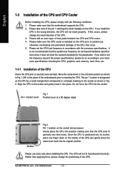
...motherboard) prior to inserting the CPU. Please add an even layer of the CPU. 3. Please make sure that the motherboard supports the CPU. 2. Move the socket lever to the unlocked position as shown in Fig. 1 (90o to see that the CPU pins fit perfectly into the socket... location is installed on the CPU. Pin One Fig.2 Pin 1 location on the middle of the CPU and CPU Cooler Before installing the CPU, please comply with the processor specifications. GA-M61PM-S2 (rev. 2.0) Motherboard - 12 - Do not force the CPU into their holes. Once the CPU is not recommended that corresponds ...
...motherboard) prior to inserting the CPU. Please add an even layer of the CPU. 3. Please make sure that the motherboard supports the CPU. 2. Move the socket lever to the unlocked position as shown in Fig. 1 (90o to see that the CPU pins fit perfectly into the socket... location is installed on the CPU. Pin One Fig.2 Pin 1 location on the middle of the CPU and CPU Cooler Before installing the CPU, please comply with the processor specifications. GA-M61PM-S2 (rev. 2.0) Motherboard - 12 - Do not force the CPU into their holes. Once the CPU is not recommended that corresponds ...

Manual
Page 15
..., chips, and speed), you wish to use memory modules of identical brand, size, chips, and speed. English Dual Channel Memory Configuration The GA-M61PM-S2 supports the Dual Channel Technology. Due to CPU limitation, if you must install them in DDRII_1 and DDRII_2 DIMM sockets. - 15 - DS/SS 4 memory modules DS/SS DS/SS DS...
..., chips, and speed), you wish to use memory modules of identical brand, size, chips, and speed. English Dual Channel Memory Configuration The GA-M61PM-S2 supports the Dual Channel Technology. Due to CPU limitation, if you must install them in DDRII_1 and DDRII_2 DIMM sockets. - 15 - DS/SS 4 memory modules DS/SS DS/SS DS...
Manual
Page 20
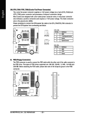
The types of FDD drives supported are designed with color-coded power connector wires. English 3/4) CPU_FAN / SYS_FAN (Cooler Fan Power Connector) The cooler fan power connector supplies a +12V power voltage via a 3-... FDD cable while the other end of the foolproof groove in the FDD connector. 34 33 2 1 GA-M61PM-S2 (rev. 2.0) Motherboard - 20 - Before attaching the FDD cable, please take note of the cable connects to prevent the CPU/system from overheating and failure. 1 CPU_FAN 1 SYS_FAN CPU_FAN: Pin No. 1 2 3 4 Definition GND +12V/Speed Control Sense...
The types of FDD drives supported are designed with color-coded power connector wires. English 3/4) CPU_FAN / SYS_FAN (Cooler Fan Power Connector) The cooler fan power connector supplies a +12V power voltage via a 3-... FDD cable while the other end of the foolproof groove in the FDD connector. 34 33 2 1 GA-M61PM-S2 (rev. 2.0) Motherboard - 20 - Before attaching the FDD cable, please take note of the cable connects to prevent the CPU/system from overheating and failure. 1 CPU_FAN 1 SYS_FAN CPU_FAN: Pin No. 1 2 3 4 Definition GND +12V/Speed Control Sense...

Manual
Page 33
Memory The category is display-only which is determined by POST (Power On Self Test) of memory located above 1 MB in the CPU's memory address map. - 33 - Extended Memory The BIOS determines how much extended memory is Enabled). 720K, 3.5" 3.5 inch double-sided drive; 720K byte capacity . ...will not stop for a keyboard or disk error; All, But Disk/Key The system boot will not stop for a disk error; Floppy 3 Mode Support (for systems with 512K memory installed on the motherboard, or 640K for Japan Area) Disabled Normal Floppy Drive. (Default value) Drive A Drive A ...
Memory The category is display-only which is determined by POST (Power On Self Test) of memory located above 1 MB in the CPU's memory address map. - 33 - Extended Memory The BIOS determines how much extended memory is Enabled). 720K, 3.5" 3.5 inch double-sided drive; 720K byte capacity . ...will not stop for a keyboard or disk error; All, But Disk/Key The system boot will not stop for a disk error; Floppy 3 Mode Support (for systems with 512K memory installed on the motherboard, or 640K for Japan Area) Disabled Normal Floppy Drive. (Default value) Drive A Drive A ...

Manual
Page 42
... CMOS, and then your computer will show "No." GA-M61PM-S2 (rev. 2.0) Motherboard - 42 - System/CPU Warning Temperature 60oC / 140oF Monitor System/CPU temperature at 60oC / 140oF. 70oC / 158oF Monitor System/CPU temperature at 70oC / 158oF. 80oC / 176oF Monitor System/CPU temperature at 80oC / 176oF. 90oC / 194oF Monitor System/CPU temperature at next boot. Current Voltage(V) Vcore / DDR2...
... CMOS, and then your computer will show "No." GA-M61PM-S2 (rev. 2.0) Motherboard - 42 - System/CPU Warning Temperature 60oC / 140oF Monitor System/CPU temperature at 60oC / 140oF. 70oC / 158oF Monitor System/CPU temperature at 70oC / 158oF. 80oC / 176oF Monitor System/CPU temperature at 80oC / 176oF. 90oC / 194oF Monitor System/CPU temperature at next boot. Current Voltage(V) Vcore / DDR2...
Manual
Page 51
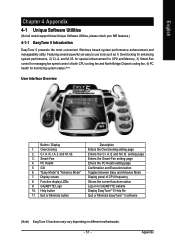
...Software Utilities (Not all model support these Unique Software Utilities, please check your MB features.) 4-1-1 EasyTune 5 Introduction EasyTune 5 presents the most convenient Windows based system performance enhancement and manageability utility. Featuring several powerful yet easy to GIGABYTE website Display EasyTuneTM 5 Help ...51 - GO 6. "Easy Mode" & "Advance Mode" 7. Appendix for special enhancement for CPU and Memory, 3) Smart-Fan control for managing fan speed control of CPU frequency Shows the current functions status Log on to use tools such as 1) Overclocking for monitoring ...
...Software Utilities (Not all model support these Unique Software Utilities, please check your MB features.) 4-1-1 EasyTune 5 Introduction EasyTune 5 presents the most convenient Windows based system performance enhancement and manageability utility. Featuring several powerful yet easy to GIGABYTE website Display EasyTuneTM 5 Help ...51 - GO 6. "Easy Mode" & "Advance Mode" 7. Appendix for special enhancement for CPU and Memory, 3) Smart-Fan control for managing fan speed control of CPU frequency Shows the current functions status Log on to use tools such as 1) Overclocking for monitoring ...

