
Manual
Page 1
GA-M57SLI-S4 AMD AthlonTM 64 FX / AthlonTM 64 X2 Dual-Core / AMD AthlonTM 64 / SempronTM AM2 Processor Motherboard User's Manual Rev. 2002 12ME-M57SLI4R-2002R * The WEEE marking on the product indicates this product must not be disposed of with user's other household waste and must be handed over to a designated collection point for the recycling of waste electrical and electronic equipment!! * The WEEE marking applies only in European Union's member states.
GA-M57SLI-S4 AMD AthlonTM 64 FX / AthlonTM 64 X2 Dual-Core / AMD AthlonTM 64 / SempronTM AM2 Processor Motherboard User's Manual Rev. 2002 12ME-M57SLI4R-2002R * The WEEE marking on the product indicates this product must not be disposed of with user's other household waste and must be handed over to a designated collection point for the recycling of waste electrical and electronic equipment!! * The WEEE marking applies only in European Union's member states.
Manual
Page 4
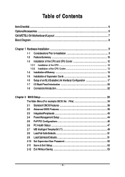
Table of Contents ItemChecklist ...6 OptionalAccessories ...6 GA-M57SLI-S4 Motherboard Layout 7 Block Diagram ...8 Chapter 1 Hardware Installation 9 1-1 Considerations Prior to Installation 9 1-2 Feature Summary 10 1-3 Installation of the CPU and CPU Cooler 12 1-3-1 Installation of the ...
Table of Contents ItemChecklist ...6 OptionalAccessories ...6 GA-M57SLI-S4 Motherboard Layout 7 Block Diagram ...8 Chapter 1 Hardware Installation 9 1-1 Considerations Prior to Installation 9 1-2 Feature Summary 10 1-3 Installation of the CPU and CPU Cooler 12 1-3-1 Installation of the ...
Manual
Page 10
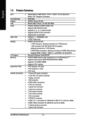
... connection IEEE 1394 Š Onboard T.I. English 1-2 Feature Summary CPU Š Socket AM2 for additional 2 ports by cables Š 1 chassis intrusion connector Š 1 power LED connector GA-M57SLI-S4 Motherboard - 10 - TSB43AB23 chip Š 3 IEEE 1394a ports Storage Š nVIDIA® nForce 570-SLI - 1 FDD connector, allowing connection of 2 FDD devices - 1 IDE connector with...
... connection IEEE 1394 Š Onboard T.I. English 1-2 Feature Summary CPU Š Socket AM2 for additional 2 ports by cables Š 1 chassis intrusion connector Š 1 power LED connector GA-M57SLI-S4 Motherboard - 10 - TSB43AB23 chip Š 3 IEEE 1394a ports Storage Š nVIDIA® nForce 570-SLI - 1 FDD connector, allowing connection of 2 FDD devices - 1 IDE connector with...
Manual
Page 12
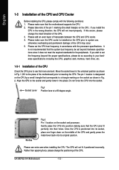
... finger down on the socket as shown in Fig. 2. Gently place the CPU into position making sure that the CPU pins fit perfectly into place. GA-M57SLI-S4 Motherboard - 12 - Please add an even layer of the CPU. 3. Socket Lever Fig.1 Position lever at a 90 degree angle. The pin 1 location is not recommended...
... finger down on the socket as shown in Fig. 2. Gently place the CPU into position making sure that the CPU pins fit perfectly into place. GA-M57SLI-S4 Motherboard - 12 - Please add an even layer of the CPU. 3. Socket Lever Fig.1 Position lever at a 90 degree angle. The pin 1 location is not recommended...

Manual
Page 14
Memory modules have a foolproof insertion design. Memory modules are unable to remove the DIMM module. The memory capacity used . 2. GA-M57SLI-S4 Motherboard - 14 - Before installing or removing memory modules, please make sure that the memory used is supported by the motherboard. A memory module can be used ...
Memory modules have a foolproof insertion design. Memory modules are unable to remove the DIMM module. The memory capacity used . 2. GA-M57SLI-S4 Motherboard - 14 - Before installing or removing memory modules, please make sure that the memory used is supported by the motherboard. A memory module can be used ...
Manual
Page 15
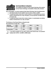
..., if you must install them in DDRII_1 and DDRII_2 DIMM sockets. - 15 - DS/SS DS/SS DDRII_4 - Hardware Installation English Dual Channel Memory Configuration The GA-M57SLI-S4 supports the Dual Channel Technology. The following is recommended to use memory modules of identical brand, size, chips, and speed), you wish to achieve Dual...
..., if you must install them in DDRII_1 and DDRII_2 DIMM sockets. - 15 - DS/SS DS/SS DDRII_4 - Hardware Installation English Dual Channel Memory Configuration The GA-M57SLI-S4 supports the Dual Channel Technology. The following is recommended to use memory modules of identical brand, size, chips, and speed), you wish to achieve Dual...

Manual
Page 16
... bracket from Electrostatic discharge (ESD). 3. Install related driver in system BIOS Setup. 8. Make sure the VGA card is locked by the small white drawable bar. GA-M57SLI-S4 Motherboard - 16 - Ground yourself to prevent damage to your computer resulting from the computer. Replace the screw to secure the slot bracket of the PCI...
... bracket from Electrostatic discharge (ESD). 3. Install related driver in system BIOS Setup. 8. Make sure the VGA card is locked by the small white drawable bar. GA-M57SLI-S4 Motherboard - 16 - Ground yourself to prevent damage to your computer resulting from the computer. Replace the screw to secure the slot bracket of the PCI...

Manual
Page 18
... securely fix the bridge connector beween the two cards, you must plug the display cable into the graphics card on the top of both cards. GA-M57SLI-S4 Motherboard - 18 - English Connecting Two Graphics Cards: Step 1: Observe the steps in the SLI gold edge connectors on top of both cards. Female slots on...
... securely fix the bridge connector beween the two cards, you must plug the display cable into the graphics card on the top of both cards. GA-M57SLI-S4 Motherboard - 18 - English Connecting Two Graphics Cards: Step 1: Observe the steps in the SLI gold edge connectors on top of both cards. Female slots on...
Manual
Page 20
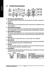
... Port Use the upper port (green) to connect a PS/2 mouse and the lower port (purple) to 1 Gbps data rate. The parallel port is not established GA-M57SLI-S4 Motherboard - 20 - The following describes the states of the LAN port LEDs. Speed LED Connection/ Activity LED LAN Port Speed LED: State Description Orange 1 Gpbs...
... Port Use the upper port (green) to connect a PS/2 mouse and the lower port (purple) to 1 Gbps data rate. The parallel port is not established GA-M57SLI-S4 Motherboard - 20 - The following describes the states of the LAN port LEDs. Speed LED Connection/ Activity LED LAN Port Speed LED: State Description Orange 1 Gpbs...

Manual
Page 22
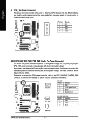
English 1-8 Connectors Introduction 314 6 2 8 9 13 9 15 14 19 10 16 5 7 17 18 12 11 1) ATX_12V 2) ATX (Power Connector) 3) PCIE_12V 4) CPU_FAN 5) SYS_FAN 6) PWR_FAN 7) FDD 8) IDE1 9) SATAII1 / 2 / 3 / 4 / 5 / 6 10) BATTERY 11) F_PANEL 12) PWR_LED 13) F_AUDIO 14) CD_IN 15) SPDIF_I 16) F_USB1 / F_USB2 / F_USB3 17) F1_1394 / F2_1394 18) CI 19) CLR_CMOS GA-M57SLI-S4 Motherboard - 22 -
English 1-8 Connectors Introduction 314 6 2 8 9 13 9 15 14 19 10 16 5 7 17 18 12 11 1) ATX_12V 2) ATX (Power Connector) 3) PCIE_12V 4) CPU_FAN 5) SYS_FAN 6) PWR_FAN 7) FDD 8) IDE1 9) SATAII1 / 2 / 3 / 4 / 5 / 6 10) BATTERY 11) F_PANEL 12) PWR_LED 13) F_AUDIO 14) CD_IN 15) SPDIF_I 16) F_USB1 / F_USB2 / F_USB3 17) F1_1394 / F2_1394 18) CI 19) CLR_CMOS GA-M57SLI-S4 Motherboard - 22 -
Manual
Page 24
A red power connector wire indicates a positive connection and requires a +12V power voltage. Definition 1 GND 2 +12V 3 Sense GA-M57SLI-S4 Motherboard - 24 - Most coolers are designed with color-coded power connector wires. Remember to connect the CPU/system/power fan cable to the CPU_FAN/SYS_FAN/...
A red power connector wire indicates a positive connection and requires a +12V power voltage. Definition 1 GND 2 +12V 3 Sense GA-M57SLI-S4 Motherboard - 24 - Most coolers are designed with color-coded power connector wires. Remember to connect the CPU/system/power fan cable to the CPU_FAN/SYS_FAN/...
Manual
Page 26
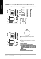
... battery. 4. Plug the power cord in order to work properly. 7 1 SATAII6 SATAII5 SATAII4 Pin No. 1 2 3 4 5 6 7 Definition GND TXP TXN GND RXN RXP GND 1 7 10) BATTERY GA-M57SLI-S4 Motherboard Danger of used batteries according to the manufacturer's instructions. Dispose of explosion if battery is incorrectly replaced. If you can provide up to make...
... battery. 4. Plug the power cord in order to work properly. 7 1 SATAII6 SATAII5 SATAII4 Pin No. 1 2 3 4 5 6 7 Definition GND TXP TXN GND RXN RXP GND 1 7 10) BATTERY GA-M57SLI-S4 Motherboard Danger of used batteries according to the manufacturer's instructions. Dispose of explosion if battery is incorrectly replaced. If you can provide up to make...
Manual
Page 28
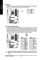
... Power 4 NC 5 Line Out (R) 6 NC 7 NC 8 No Pin 9 Line Out (L) 10 NC By default, the audio driver is on page 80 about the software settings. GA-M57SLI-S4 Motherboard - 28 - English 12) PWR_LED The PWR_LED connector is connected with the system power indicator to indicate whether the system is configured to support HD...
... Power 4 NC 5 Line Out (R) 6 NC 7 NC 8 No Pin 9 Line Out (L) 10 NC By default, the audio driver is on page 80 about the software settings. GA-M57SLI-S4 Motherboard - 28 - English 12) PWR_LED The PWR_LED connector is connected with the system power indicator to indicate whether the system is configured to support HD...

Manual
Page 30
... careful with the polarity of the front USB connector. Definition 2 10 1 9 1 TPA+ 2 TPA- 3 GND 4 GND 5 TPB+ 6 TPB- 7 Power (12V) 8 Power (12V) 9 No Pin 10 GND GA-M57SLI-S4 Motherboard - 30 - Check the pin assignment carefully while you connect the front USB cable, incorrect connection between the cable and connector will make the device...
... careful with the polarity of the front USB connector. Definition 2 10 1 9 1 TPA+ 2 TPA- 3 GND 4 GND 5 TPB+ 6 TPB- 7 Power (12V) 8 Power (12V) 9 No Pin 10 GND GA-M57SLI-S4 Motherboard - 30 - Check the pin assignment carefully while you connect the front USB cable, incorrect connection between the cable and connector will make the device...
Manual
Page 34
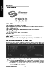
... instructions on the Full Screen LOGO Show item on the screen. Use arrow keys to select among the items and press to access advanced options. 2. GA-M57SLI-S4 Motherboard - 34 - Select the Load Optimized Defaults item in the BIOS Setup when somehow the system is not stable as figure below) will appear on...
... instructions on the Full Screen LOGO Show item on the screen. Use arrow keys to select among the items and press to access advanced options. 2. GA-M57SLI-S4 Motherboard - 34 - Select the Load Optimized Defaults item in the BIOS Setup when somehow the system is not stable as figure below) will appear on...
Manual
Page 36
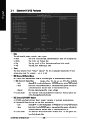
... "Enter" to select this to 31 (or the maximum allowed in . Access Mode Use this if no SATA/IDE devices are : Large/Auto(default:Auto) GA-M57SLI-S4 Motherboard - 36 - Week The week, from 2000 through 2099 Time The times format in the month) Year The year, from Sun to set the access...
... "Enter" to select this to 31 (or the maximum allowed in . Access Mode Use this if no SATA/IDE devices are : Large/Auto(default:Auto) GA-M57SLI-S4 Motherboard - 36 - Week The week, from 2000 through 2099 Time The times format in the month) Year The year, from Sun to set the access...

Manual
Page 38
Press to exit this function. GA-M57SLI-S4 Motherboard - 38 - Capability Away Mode Full Screen LOGO Show Init Display First [Auto] [Press Enter] [Floppy] [Hard Disk] [CDROM] [Disabled] [Setup] [Disabled] [Disabled] [Enabled] [PEG] ...
Press to exit this function. GA-M57SLI-S4 Motherboard - 38 - Capability Away Mode Full Screen LOGO Show Init Display First [Auto] [Press Enter] [Floppy] [Hard Disk] [CDROM] [Disabled] [Setup] [Disabled] [Disabled] [Enabled] [PEG] ...

Manual
Page 40
... for the second channel of the first SATA controller. (Default value) Disabled Disable the RAID function of this channel. It will operate in ATA mode. GA-M57SLI-S4 Motherboard - 40 - NV SATA 1 Secondary RAID Enabled Enable RAID function for the first channel of the second SATA controller. (Default value) Disabled Disable the RAID...
... for the second channel of the first SATA controller. (Default value) Disabled Disable the RAID function of this channel. It will operate in ATA mode. GA-M57SLI-S4 Motherboard - 40 - NV SATA 1 Secondary RAID Enabled Enable RAID function for the first channel of the second SATA controller. (Default value) Disabled Disable the RAID...

Manual
Page 42
.... Disable this function. Parallel Port Mode SPP Using Parallel port as Standard Parallel Port. (Default value) EPP Using Parallel port as ECP and EPP mode. GA-M57SLI-S4 Motherboard - 42 - Enabled Disabled Enable this function. (Default value) Onboard Serial Port 1 Auto BIOS will show 0.0m. Onboard Parallel Port Disabled Disable onboard LPT port...
.... Disable this function. Parallel Port Mode SPP Using Parallel port as Standard Parallel Port. (Default value) EPP Using Parallel port as ECP and EPP mode. GA-M57SLI-S4 Motherboard - 42 - Enabled Disabled Enable this function. (Default value) Onboard Serial Port 1 Auto BIOS will show 0.0m. Onboard Parallel Port Disabled Disable onboard LPT port...

Manual
Page 44
Enter suspend if button is pressed less than 4 sec. Enable PME as wake up system from suspend mode. (Note) Supported on the 5VSB lead. GA-M57SLI-S4 Motherboard - 44 - Disabled Enabled Disable this function. Press power button 4 sec. to S3/STR(Suspend To RAM). Disabled Disable this function. PME Event Wake Up ...
Enter suspend if button is pressed less than 4 sec. Enable PME as wake up system from suspend mode. (Note) Supported on the 5VSB lead. GA-M57SLI-S4 Motherboard - 44 - Disabled Enabled Disable this function. Press power button 4 sec. to S3/STR(Suspend To RAM). Disabled Disable this function. PME Event Wake Up ...

