
Manual
Page 10
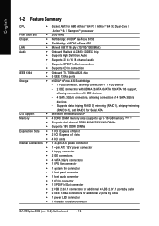
...CPU fan connector Š 1 system fan connector Š 1 front panel connector Š 1 front audio connector Š 1 CD In connector Š 1 S/PDIF In/Out connector Š 2 USB 2.0/1.1 connectors for additional 4 USB 2.0/1.1 ports by cable Š 1 power LED connector Š 1 Chassis Intrusion connector GA-M55plus-S3G... (rev. 3.0) Motherboard - 10 - TSB43AB23 chip Š 3 IEEE 1394a ports Storage Š nVIDIA® nForce 430 Southbridge - 1 FDD connector, allowing connection of 1 FDD device - 2 IDE connectors with UDMA 33/ATA 66/ATA 100/ATA 133 support,...
...CPU fan connector Š 1 system fan connector Š 1 front panel connector Š 1 front audio connector Š 1 CD In connector Š 1 S/PDIF In/Out connector Š 2 USB 2.0/1.1 connectors for additional 4 USB 2.0/1.1 ports by cable Š 1 power LED connector Š 1 Chassis Intrusion connector GA-M55plus-S3G... (rev. 3.0) Motherboard - 10 - TSB43AB23 chip Š 3 IEEE 1394a ports Storage Š nVIDIA® nForce 430 Southbridge - 1 FDD connector, allowing connection of 1 FDD device - 2 IDE connectors with UDMA 33/ATA 66/ATA 100/ATA 133 support,...
Manual
Page 11
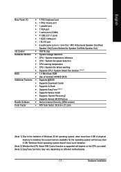
.../Subwoofer Speaker Out/Side Speaker Out) I/O Control Š IT8716 chip Hardware Monitor Š System voltage detection Š CPU / System temperature detection Š CPU / System fan speed detection Š CPU warning temperature Š CPU / System fan failure warning Š Supports CPU / System Smart Fan function (Note 2) BIOS Š 1 4 Mbit flash ROM Š Use of licensed AWARD BIOS...
.../Subwoofer Speaker Out/Side Speaker Out) I/O Control Š IT8716 chip Hardware Monitor Š System voltage detection Š CPU / System temperature detection Š CPU / System fan speed detection Š CPU warning temperature Š CPU / System fan failure warning Š Supports CPU / System Smart Fan function (Note 2) BIOS Š 1 4 Mbit flash ROM Š Use of licensed AWARD BIOS...
Manual
Page 12
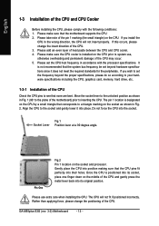
... frequency in Fig. 2. Once the CPU is not recommended that the CPU pins fit perfectly into the socket. GA-M55plus-S3G (rev. 3.0) Motherboard - 12 - If you install the CPU in Fig. 1 (90o to the plane of the motherboard) prior to a triangle marking on the CPU by a small triangle that the motherboard supports the CPU. 2. The pin 1 location is installed...
... frequency in Fig. 2. Once the CPU is not recommended that the CPU pins fit perfectly into the socket. GA-M55plus-S3G (rev. 3.0) Motherboard - 12 - If you install the CPU in Fig. 1 (90o to the plane of the motherboard) prior to a triangle marking on the CPU by a small triangle that the motherboard supports the CPU. 2. The pin 1 location is installed...
Manual
Page 15
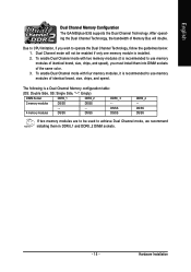
... Channel mode will double. To enable Dual Channel mode with two memory modules (it is installed. 2. The following is recommended to CPU limitation, if you must install them into DIMM sockets of identical brand, size, chips, and speed), you wish to achieve Dual Channel...Single Side, "--": Empty) DIMM Socket DDRII_1 DDRII_2 DDRII_ 3 2 memory modules DS/SS DS/SS - - - - - - English Dual Channel Memory Configuration The GA-M55plus-S3G supports the Dual Channel Technology. DS/SS DS/SS If two memory modules are to be enabled if only one memory module is recommended to use...
... Channel mode will double. To enable Dual Channel mode with two memory modules (it is installed. 2. The following is recommended to CPU limitation, if you must install them into DIMM sockets of identical brand, size, chips, and speed), you wish to achieve Dual Channel...Single Side, "--": Empty) DIMM Socket DDRII_1 DDRII_2 DDRII_ 3 2 memory modules DS/SS DS/SS - - - - - - English Dual Channel Memory Configuration The GA-M55plus-S3G supports the Dual Channel Technology. DS/SS DS/SS If two memory modules are to be enabled if only one memory module is recommended to use...
Manual
Page 20
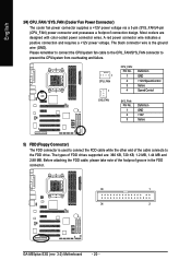
..., please take note of FDD drives supported are designed with color-coded power connector wires. The types of the foolproof groove in the FDD connector. 33 1 34 2 GA-M55plus-S3G (rev. 3.0) Motherboard - 20 - Please remember to connect the CPU/system fan cable to the CPU_FAN/SYS_FAN... connector to prevent the CPU/system from overheating and failure. 1 CPU_FAN 1 CPU_FAN: Pin No. 1 2 3 4...
..., please take note of FDD drives supported are designed with color-coded power connector wires. The types of the foolproof groove in the FDD connector. 33 1 34 2 GA-M55plus-S3G (rev. 3.0) Motherboard - 20 - Please remember to connect the CPU/system fan cable to the CPU_FAN/SYS_FAN... connector to prevent the CPU/system from overheating and failure. 1 CPU_FAN 1 CPU_FAN: Pin No. 1 2 3 4...
Manual
Page 33
... a keyboard error; Memory The category is display-only which is 3 mode Floppy Drive. This is detected during the POST. Floppy 3 Mode Support (for systems with 512K memory installed on The category determines whether the computer will not stop for the hard drive. The value of base ...(or conventional) memory installed in the CPU's memory address map. - 33 - All Errors Whenever the BIOS detects a non-fatal error the system will not stop for a keyboard or...
... a keyboard error; Memory The category is display-only which is 3 mode Floppy Drive. This is detected during the POST. Floppy 3 Mode Support (for systems with 512K memory installed on The category determines whether the computer will not stop for the hard drive. The value of base ...(or conventional) memory installed in the CPU's memory address map. - 33 - All Errors Whenever the BIOS detects a non-fatal error the system will not stop for a keyboard or...
Manual
Page 43
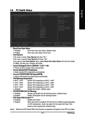
... show "No." If the case is supported will depend on CPU temperature. CPU Warning Temperature 60oC / 140oF Monitor CPU temperature at 60oC / 140oF. 70oC / 158oF Monitor CPU temperature at 70oC / 158oF. 80oC / 176oF Monitor CPU temperature at 80oC / 176oF. 90oC / 194oF Monitor CPU temperature at different speed depending on the CPU you want to reset Case Opened value...
... show "No." If the case is supported will depend on CPU temperature. CPU Warning Temperature 60oC / 140oF Monitor CPU temperature at 60oC / 140oF. 70oC / 158oF Monitor CPU temperature at 70oC / 158oF. 80oC / 176oF Monitor CPU temperature at 80oC / 176oF. 90oC / 194oF Monitor CPU temperature at different speed depending on the CPU you want to reset Case Opened value...
Manual
Page 45
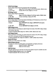
... Northbridge, its PCI Express bus, and the HT-Link between CPU and Northbridge. NB/PCIE/HT-Link Voltage Set the voltage settings for Southbridge. Supports adjustable CPU voltage from 1.850V to 2.450V. (Default value: Auto) CPU Voltage Control Please note that by 2%~16%. Disabled Disable this ..., damage to the memory may occur. Supports adjustable DDR2 voltage from 0.8000V to 1.5500V. (Default value: Normal) Normal CPU Vcore Displays your system through the increase of the CPU voltage, damage to the CPU or decrease in the CPU life expectancy may occur. BIOS Setup Normal...
... Northbridge, its PCI Express bus, and the HT-Link between CPU and Northbridge. NB/PCIE/HT-Link Voltage Set the voltage settings for Southbridge. Supports adjustable CPU voltage from 1.850V to 2.450V. (Default value: Auto) CPU Voltage Control Please note that by 2%~16%. Disabled Disable this ..., damage to the memory may occur. Supports adjustable DDR2 voltage from 0.8000V to 1.5500V. (Default value: Normal) Normal CPU Vcore Displays your system through the increase of the CPU voltage, damage to the CPU or decrease in the CPU life expectancy may occur. BIOS Setup Normal...
Manual
Page 53
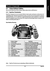
... of CPU frequency Shows the current functions status Log on to use tools such as 1) Overclocking for monitoring system status.(Note) User Interface Overview Button / Display 1. C.I.A./C.I.A.2 and M.I .A. PC Health 5. Function display LEDs 9. Help button 11. Smart-Fan 4. Display screen 8. GIGABYTE Logo 10. English Chapter 4 Appendix 4-1 Unique Software Utilities (Not all model support these...
... of CPU frequency Shows the current functions status Log on to use tools such as 1) Overclocking for monitoring system status.(Note) User Interface Overview Button / Display 1. C.I.A./C.I.A.2 and M.I .A. PC Health 5. Function display LEDs 9. Help button 11. Smart-Fan 4. Display screen 8. GIGABYTE Logo 10. English Chapter 4 Appendix 4-1 Unique Software Utilities (Not all model support these...

