
Manual
Page 4
Table of Contents ItemChecklist ...6 OptionalAccessories ...6 GA-M55plus-S3G (rev. 3.0) Motherboard Layout 7 Block Diagram ...8 Chapter 1 Hardware Installation 9 1-1 Considerations Prior to Installation 9 1-2 Feature Summary 10 1-3 Installation of the CPU and CPU Cooler 12 1-3-1 Installation of the CPU 12 1-3-2 Installation of the CPU Cooler 13 1-4 Installation of Memory 14 1-5 Installation of Expansion Cards 16 1-6 I/O Back Panel Introduction 17...
Table of Contents ItemChecklist ...6 OptionalAccessories ...6 GA-M55plus-S3G (rev. 3.0) Motherboard Layout 7 Block Diagram ...8 Chapter 1 Hardware Installation 9 1-1 Considerations Prior to Installation 9 1-2 Feature Summary 10 1-3 Installation of the CPU and CPU Cooler 12 1-3-1 Installation of the CPU 12 1-3-2 Installation of the CPU Cooler 13 1-4 Installation of Memory 14 1-5 Installation of Expansion Cards 16 1-6 I/O Back Panel Introduction 17...
Manual
Page 8
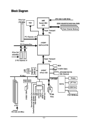
... PCIe CLK (100 MHz) VGA AMD Socket AM2 CPU CPU CLK+/-(200 MHz) DDRII 800/667/533/400 MHz DIMM Hyper Transport Bus Dual Channel Memory PCI Express x16 PCI Express Bus x1 x1 PCIe CLK (100 MHz) 2 PCI Express x1 PCI Bus TSB43AB23 LAN RJ45 Marvell 88E1116 nVIDIA® GeForce...
... PCIe CLK (100 MHz) VGA AMD Socket AM2 CPU CPU CLK+/-(200 MHz) DDRII 800/667/533/400 MHz DIMM Hyper Transport Bus Dual Channel Memory PCI Express x16 PCI Express Bus x1 x1 PCIe CLK (100 MHz) 2 PCI Express x1 PCI Bus TSB43AB23 LAN RJ45 Marvell 88E1116 nVIDIA® GeForce...
Manual
Page 10
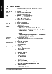
... striping+mirroring (RAID 0+1), and RAID 5 for Serial ATA O.S Support Š Microsoft Windows 2000/XP Memory Š 4 DDRII DIMM memory slots (supports up to 16 GB memory) (Note 1) Š Supports dual channel DDRII 800/667/533/400 DIMMs Š Supports 1.8V ...In/Out connector Š 2 USB 2.0/1.1 connectors for additional 4 USB 2.0/1.1 ports by cable Š 1 power LED connector Š 1 Chassis Intrusion connector GA-M55plus-S3G (rev. 3.0) Motherboard - 10 - TSB43AB23 chip Š 3 IEEE 1394a ports Storage Š nVIDIA® nForce 430 Southbridge - 1 FDD connector, allowing...
... striping+mirroring (RAID 0+1), and RAID 5 for Serial ATA O.S Support Š Microsoft Windows 2000/XP Memory Š 4 DDRII DIMM memory slots (supports up to 16 GB memory) (Note 1) Š Supports dual channel DDRII 800/667/533/400 DIMMs Š Supports 1.8V ...In/Out connector Š 2 USB 2.0/1.1 connectors for additional 4 USB 2.0/1.1 ports by cable Š 1 power LED connector Š 1 Chassis Intrusion connector GA-M55plus-S3G (rev. 3.0) Motherboard - 10 - TSB43AB23 chip Š 3 IEEE 1394a ports Storage Š nVIDIA® nForce 430 Southbridge - 1 FDD connector, allowing...
Manual
Page 11
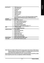
... Š ATX form factor; 30.5cm x 21.3cm (Note 1) Due to the limitation of Windows 32-bit operating system, when more than 4 GB of physical memory is supported will be less than 4 GB; Windows 64-bit operating system doesn't have such limitation. (Note 2) Whether the CPU Smart FAN Control function is...
... Š ATX form factor; 30.5cm x 21.3cm (Note 1) Due to the limitation of Windows 32-bit operating system, when more than 4 GB of physical memory is supported will be less than 4 GB; Windows 64-bit operating system doesn't have such limitation. (Note 2) Whether the CPU Smart FAN Control function is...
Manual
Page 12
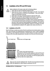
... holes. If you wish to set beyond the proper specifications, please do so according to your hardware specifications including the CPU, graphics card, memory, hard drive, etc. 1-3-1 Installation of the CPU Check the CPU pins to see that the CPU pins fit perfectly into its socket, ... motherboard) prior to system use extra care when installing the CPU. Pin One Fig.2 Pin 1 location on the CPU prior to inserting the CPU. GA-M55plus-S3G (rev. 3.0) Motherboard - 12 - If this occurs, please change the positioning of the CPU. Please make sure that the system bus frequency be...
... holes. If you wish to set beyond the proper specifications, please do so according to your hardware specifications including the CPU, graphics card, memory, hard drive, etc. 1-3-1 Installation of the CPU Check the CPU pins to see that the CPU pins fit perfectly into its socket, ... motherboard) prior to system use extra care when installing the CPU. Pin One Fig.2 Pin 1 location on the CPU prior to inserting the CPU. GA-M55plus-S3G (rev. 3.0) Motherboard - 12 - If this occurs, please change the positioning of the CPU. Please make sure that the system bus frequency be...
Manual
Page 14
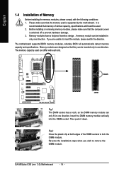
...installed in only one direction. Fig.2 Close the plastic clip at both edges of Memory Before installing the memory modules, please comply with each slot. Please make sure that the memory used is recommended that they can be used can only fit in one direction....a notch, so the DIMM memory module can differ with the following conditions: 1. If you wish to insert the module, please switch the direction. The memory capacity used . 2. Then push it down. It is supported by the motherboard. GA-M55plus-S3G (rev. 3.0) Motherboard - 14 - Memory modules are unable to remove ...
...installed in only one direction. Fig.2 Close the plastic clip at both edges of Memory Before installing the memory modules, please comply with each slot. Please make sure that the memory used is recommended that they can be used can only fit in one direction....a notch, so the DIMM memory module can differ with the following conditions: 1. If you wish to insert the module, please switch the direction. The memory capacity used . 2. Then push it down. It is supported by the motherboard. GA-M55plus-S3G (rev. 3.0) Motherboard - 14 - Memory modules are unable to remove ...
Manual
Page 15
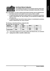
...must install them in DDRII_1 and DDRII_2 DIMM sockets. - 15 - After operating the Dual Channel Technology, the bandwidth of Memory Bus will not be used to use memory modules of the same color. 3. Dual Channel mode will double. To enable Dual Channel mode with four.../SS DS/SS If two memory modules are to be enabled if only one memory module is recommended to achieve Dual Channel mode, we recommend installing them into DIMM sockets of identical brand, size, chips, and speed. English Dual Channel Memory Configuration The GA-M55plus-S3G supports the Dual Channel Technology....
...must install them in DDRII_1 and DDRII_2 DIMM sockets. - 15 - After operating the Dual Channel Technology, the bandwidth of Memory Bus will not be used to use memory modules of the same color. 3. Dual Channel mode will double. To enable Dual Channel mode with four.../SS DS/SS If two memory modules are to be enabled if only one memory module is recommended to achieve Dual Channel mode, we recommend installing them into DIMM sockets of identical brand, size, chips, and speed. English Dual Channel Memory Configuration The GA-M55plus-S3G supports the Dual Channel Technology....
Manual
Page 32
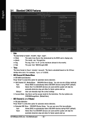
The time is , , , . IDE Channel 0/1, Master/Slave IDE/SATA Device Setup. GA-M55plus-S3G (rev. 3.0) Motherboard - 32 - to Dec. to Sat. Drive A Floppy 3 Mode Support Halt On Base Memory Extended Memory [1.44M, 3.5"] [Disabled] [All, But Keyboard] 640K 511M 1 to 31 (or maximum allowed in the month) 1999 to 2098 KLJI: Move Enter: Select F5: Previous Values...
The time is , , , . IDE Channel 0/1, Master/Slave IDE/SATA Device Setup. GA-M55plus-S3G (rev. 3.0) Motherboard - 32 - to Dec. to Sat. Drive A Floppy 3 Mode Support Halt On Base Memory Extended Memory [1.44M, 3.5"] [Disabled] [All, But Keyboard] 640K 511M 1 to 31 (or maximum allowed in the month) 1999 to 2098 KLJI: Move Enter: Select F5: Previous Values...
Manual
Page 33
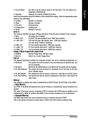
... computer will determine the amount of the BIOS. No Errors The system boot will not stop for all other errors. Extended Memory The BIOS determines how much extended memory is detected during the POST. BIOS Setup All, But Disk/Key The system boot will not stop for Japan Area) Disabled... this information. Hard drive information should be stopped. Halt on the motherboard. it will stop for any error that has been installed in the CPU's memory address map. - 33 - it will stop for the hard drive. The value of floppy disk drive A that may be detected and you will...
... computer will determine the amount of the BIOS. No Errors The system boot will not stop for all other errors. Extended Memory The BIOS determines how much extended memory is detected during the POST. BIOS Setup All, But Disk/Key The system boot will not stop for Japan Area) Disabled... this information. Hard drive information should be stopped. Halt on the motherboard. it will stop for any error that has been installed in the CPU's memory address map. - 33 - it will stop for the hard drive. The value of floppy disk drive A that may be detected and you will...
Manual
Page 44
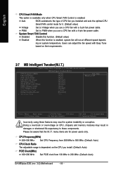
... and sets the optimal CPU Smart FAN control mode for power users only. ing on CPU, chipsets and memory modules may result in damages or shortened life expectancy to 200 MHz. (Default: Auto) GA-M55plus-S3G (rev. 3.0) Motherboard - 44 - English CPU Smart FAN Mode This option is available only when CPU Smart FAN Control...
... and sets the optimal CPU Smart FAN control mode for power users only. ing on CPU, chipsets and memory modules may result in damages or shortened life expectancy to 200 MHz. (Default: Auto) GA-M55plus-S3G (rev. 3.0) Motherboard - 44 - English CPU Smart FAN Mode This option is available only when CPU Smart FAN Control...
Manual
Page 45
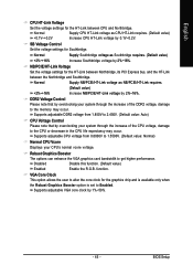
...%. SB Voltage Control Set the voltage settings for the graphics chip and is available only when the Robust Graphics Booster option is set to the memory may occur. Supports adjustable CPU voltage from 1.850V to alter the core clock for Southbridge. VGA Core Clock This option allows the user to 2.450V...
...%. SB Voltage Control Set the voltage settings for the graphics chip and is available only when the Robust Graphics Booster option is set to the memory may occur. Supports adjustable CPU voltage from 1.850V to alter the core clock for Southbridge. VGA Core Clock This option allows the user to 2.450V...
Manual
Page 53
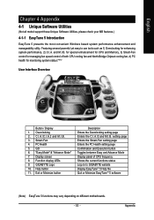
for special enhancement for CPU and Memory, 3) Smart-Fan control for managing fan speed control of CPU frequency Shows the current functions status Log on different motherboards. - 53 - GO 6. ... performance, 2) C.I .B. C.I.A./C.I.A.2 and M.I .B. Exit or Minimize button Description Enters the Overclocking setting page Enters the C.I.A./2 and M.I .A. Featuring several powerful yet easy to GIGABYTE website Display EasyTuneTM 5 Help file Quit or Minimize EasyTuneTM 5 software (Note) EasyTune 5 functions may vary depending on to use tools such as 1) Overclocking for monitoring...
for special enhancement for CPU and Memory, 3) Smart-Fan control for managing fan speed control of CPU frequency Shows the current functions status Log on different motherboards. - 53 - GO 6. ... performance, 2) C.I .B. C.I.A./C.I.A.2 and M.I .B. Exit or Minimize button Description Enters the Overclocking setting page Enters the C.I.A./2 and M.I .A. Featuring several powerful yet easy to GIGABYTE website Display EasyTuneTM 5 Help file Quit or Minimize EasyTuneTM 5 software (Note) EasyTune 5 functions may vary depending on to use tools such as 1) Overclocking for monitoring...
Manual
Page 54
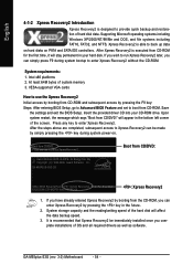
...CD-ROM. After the steps above are completed, subsequent access to Xpress Recovery2 can be immediately installed once you complete installations of hard disk data. GA-M55PLUS-S3G D3 . . . . :BIOS Setup/Q-Flash, : Xpress Recovery2, :For Boot Menu 10/25/2006-C51-MCP51-6A61HG0MC-00 : Xpress Recovery2 ... time, it will stay permanent in the bottom left corner of system memory 3. If you wish to run Xpress Recovery2 later, you can simply press F9 during system power-on PATA and SATA IDE controllers. GA-M55plus-S3G (rev. 3.0) Motherboard - 54 - Upon system restart, the message ...
...CD-ROM. After the steps above are completed, subsequent access to Xpress Recovery2 can be immediately installed once you complete installations of hard disk data. GA-M55PLUS-S3G D3 . . . . :BIOS Setup/Q-Flash, : Xpress Recovery2, :For Boot Menu 10/25/2006-C51-MCP51-6A61HG0MC-00 : Xpress Recovery2 ... time, it will stay permanent in the bottom left corner of system memory 3. If you wish to run Xpress Recovery2 later, you can simply press F9 during system power-on PATA and SATA IDE controllers. GA-M55plus-S3G (rev. 3.0) Motherboard - 54 - Upon system restart, the message ...

Manual
Page 56
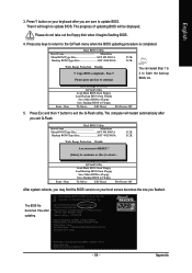
.../ Dual BIOS / Q-Flash / F9 For Xpress Recovery 08/07/2003-i875P-6A79BG03C-00 GA-M55plus-S3G (rev. 3.0) Motherboard - 56 - Reboot your motherboard has dual-BIOS, please refer to avoid any claims from Gigabyte's website. 2. If your motherboard from end-users. This section only deals with the Q-...BIOS for 8KNXP Ultra Fa3 Check System Health OK , VCore = 1.5250 Main Processor : Intel Pentium(R) 4 1.6GHz (133x12) Memory Testing : 131072K OK Memory Frequency 266 MHz in Flash ROM. Part One: Updating BIOS with model name.Fxx. Intel i875P AGPset BIOS for your motherboard has ...
.../ Dual BIOS / Q-Flash / F9 For Xpress Recovery 08/07/2003-i875P-6A79BG03C-00 GA-M55plus-S3G (rev. 3.0) Motherboard - 56 - Reboot your motherboard has dual-BIOS, please refer to avoid any claims from Gigabyte's website. 2. If your motherboard from end-users. This section only deals with the Q-...BIOS for 8KNXP Ultra Fa3 Check System Health OK , VCore = 1.5250 Main Processor : Intel Pentium(R) 4 1.6GHz (133x12) Memory Testing : 131072K OK Memory Frequency 266 MHz in Flash ROM. Part One: Updating BIOS with model name.Fxx. Intel i875P AGPset BIOS for your motherboard has ...
Manual
Page 59
... flashing BIOS. 4. English 3. Intel i875P AGPset BIOS for 8KNXP Ultra Fba Check System Health OK , VCore = 1.5250 Main Processor : Intel Pentium(R) 4 1.6GHz (133x12) Memory Testing : 131072K OK Memory Frequency 266 MHz in Single Channel Primary Master : FUJITSU MPE3170AT ED-03-08 Primary Slave : None Secondary Master : CREATIVEDVD-RM DVD1242E BC101 Secondary Slave...
... flashing BIOS. 4. English 3. Intel i875P AGPset BIOS for 8KNXP Ultra Fba Check System Health OK , VCore = 1.5250 Main Processor : Intel Pentium(R) 4 1.6GHz (133x12) Memory Testing : 131072K OK Memory Frequency 266 MHz in Single Channel Primary Master : FUJITSU MPE3170AT ED-03-08 Primary Slave : None Secondary Master : CREATIVEDVD-RM DVD1242E BC101 Secondary Slave...
Manual
Page 62
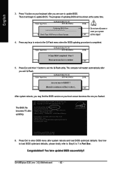
... Check System Health OK Main Processor : Intel Pentium(R) 4 1.7GHz (100x17.0) Memory Testing : 122880K OK + 8192K Shared Memory Primary Master : FUJITSU MPE3170AT ED-03-08 Primary Slave : None Secondary Master : CREATIVEDVD-RM DVD1242E BC101 Secondary Slave : None Press DEL to 7 in Part One. English 3. GA-M55plus-S3G (rev. 3.0) Motherboard - 62 - Press Esc and then Y button to...
... Check System Health OK Main Processor : Intel Pentium(R) 4 1.7GHz (100x17.0) Memory Testing : 122880K OK + 8192K Shared Memory Primary Master : FUJITSU MPE3170AT ED-03-08 Primary Slave : None Secondary Master : CREATIVEDVD-RM DVD1242E BC101 Secondary Slave : None Press DEL to 7 in Part One. English 3. GA-M55plus-S3G (rev. 3.0) Motherboard - 62 - Press Esc and then Y button to...
Manual
Page 68
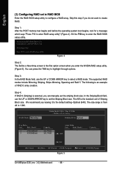
...Disks Port Disk Model [ ] Add Capacity [ ] Del [ESC] Quit [F6] Back [F7] Finish [TAB] Navigate [ ] Select [ENTER] Popup Figure 5 GA-M55plus-S3G (rev. 3.0) Motherboard - 68 - English (3) Configuring RAID set the Striping Block size. Figure 4 Step 2: The Define a New Array screen is from 4K to ... Define a New Array - The supported RAID modes include Mirroring, Striping, Stripe Mirroring, Spanning and Raid 5. Step 1: After the POST memory test begins and before the operating system boot begins, look for a message which says "Press F10 to enter the RAID BIOS setup utility...
...Disks Port Disk Model [ ] Add Capacity [ ] Del [ESC] Quit [F6] Back [F7] Finish [TAB] Navigate [ ] Select [ENTER] Popup Figure 5 GA-M55plus-S3G (rev. 3.0) Motherboard - 68 - English (3) Configuring RAID set the Striping Block size. Figure 4 Step 2: The Define a New Array screen is from 4K to ... Define a New Array - The supported RAID modes include Mirroring, Striping, Stripe Mirroring, Spanning and Raid 5. Step 1: After the POST memory test begins and before the operating system boot begins, look for a message which says "Press F10 to enter the RAID BIOS setup utility...


