Manual
Page 1
GA-M55S-S3 (rev. 2.0) AMD Socket AM2 Processor Motherboard User's Manual Rev. 2002 12ME-M55S3R-2002R * The WEEE marking on the product indicates this product must not be disposed of with user's other household waste and must be handed over to a designated collection point for the recycling of waste electrical and electronic equipment!! * The WEEE marking applies only in European Union's member states.
GA-M55S-S3 (rev. 2.0) AMD Socket AM2 Processor Motherboard User's Manual Rev. 2002 12ME-M55S3R-2002R * The WEEE marking on the product indicates this product must not be disposed of with user's other household waste and must be handed over to a designated collection point for the recycling of waste electrical and electronic equipment!! * The WEEE marking applies only in European Union's member states.
Manual
Page 2
Motherboard GA-M55S-S3 (rev. 2.0) Nov. 10, 2006 Motherboard GA-M55S-S3 (rev. 2.0) Nov. 10, 2006
Motherboard GA-M55S-S3 (rev. 2.0) Nov. 10, 2006 Motherboard GA-M55S-S3 (rev. 2.0) Nov. 10, 2006
Manual
Page 4
Table of Contents ItemChecklist ...6 OptionalAccessories ...6 GA-M55S-S3 (rev. 2.0) Motherboard Layout 7 Block Diagram ...8 Chapter 1 Hardware Installation 9 1-1 Considerations Prior to Installation 9 1-2 Feature Summary 10 1-3 Installation of the CPU and CPU Cooler 12 1-3-1 Installation of the ...
Table of Contents ItemChecklist ...6 OptionalAccessories ...6 GA-M55S-S3 (rev. 2.0) Motherboard Layout 7 Block Diagram ...8 Chapter 1 Hardware Installation 9 1-1 Considerations Prior to Installation 9 1-2 Feature Summary 10 1-3 Installation of the CPU and CPU Cooler 12 1-3-1 Installation of the ...
Manual
Page 7
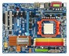
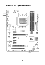
GA-M55S-S3 (rev. 2.0) Motherboard Layout CPU_FAN KB_MS ATX_12V ATX SPDIF_O SPDIFO_OPT Socket AM2 COMA LPT PWR_FAN USB 1394 USB LAN1 Marvell 88E1116 AUDIO PCIE_12V F_AUDIO PCIE_1 CODEC PCIE_16_1 PCIE_2 SPDIF_I CD_IN PCIE_3 PCIE_4 PCI1 IT8716 PCI2 REV: 2.0 FDD DDRII_1 DDRII_2 DDRII_3 DDRII_4 GA-M55S-S3 IDE1 SATAII4 SATAII1 SATAII2 SATAII3 BIOS nVIDIA® nForce 550 CLR_CMOS TSB43AB23 BATTERY F_USB3 F_USB2 F_USB1 F1_1394 F2_1394 CI F_PANEL PWR_LED SYS_FAN - 7 -
GA-M55S-S3 (rev. 2.0) Motherboard Layout CPU_FAN KB_MS ATX_12V ATX SPDIF_O SPDIFO_OPT Socket AM2 COMA LPT PWR_FAN USB 1394 USB LAN1 Marvell 88E1116 AUDIO PCIE_12V F_AUDIO PCIE_1 CODEC PCIE_16_1 PCIE_2 SPDIF_I CD_IN PCIE_3 PCIE_4 PCI1 IT8716 PCI2 REV: 2.0 FDD DDRII_1 DDRII_2 DDRII_3 DDRII_4 GA-M55S-S3 IDE1 SATAII4 SATAII1 SATAII2 SATAII3 BIOS nVIDIA® nForce 550 CLR_CMOS TSB43AB23 BATTERY F_USB3 F_USB2 F_USB1 F1_1394 F2_1394 CI F_PANEL PWR_LED SYS_FAN - 7 -
Manual
Page 10
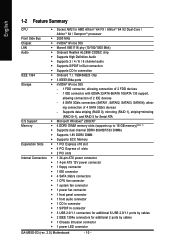
... Š 1 CD In connector Š 1 S/PDIF In connector Š 3 USB 2.0/1.1 connectors for additional 6 USB 2.0/1.1 ports by cables Š 1 Chassis Intrusion connector Š 1 power LED connector GA-M55S-S3 (rev. 2.0) Motherboard - 10 - English 1-2 Feature Summary CPU Š Socket AM2 for additional 2 ports by cables Š 2 IEEE 1394a connectors for AMD AthlonTM 64 FX / AthlonTM 64...
... Š 1 CD In connector Š 1 S/PDIF In connector Š 3 USB 2.0/1.1 connectors for additional 6 USB 2.0/1.1 ports by cables Š 1 Chassis Intrusion connector Š 1 power LED connector GA-M55S-S3 (rev. 2.0) Motherboard - 10 - English 1-2 Feature Summary CPU Š Socket AM2 for additional 2 ports by cables Š 2 IEEE 1394a connectors for AMD AthlonTM 64 FX / AthlonTM 64...
Manual
Page 12
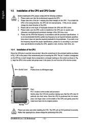
... change the insert direction of the CPU. Pin One Fig.2 Pin 1 location on the socket as shown in Fig. 2. The CPU will not insert properly. GA-M55S-S3 (rev. 2.0) Motherboard - 12 - If this occurs, please change the positioning of the CPU. 3. Please set the CPU host frequency in the wrong direction, the CPU will...
... change the insert direction of the CPU. Pin One Fig.2 Pin 1 location on the socket as shown in Fig. 2. The CPU will not insert properly. GA-M55S-S3 (rev. 2.0) Motherboard - 12 - If this occurs, please change the positioning of the CPU. 3. Please set the CPU host frequency in the wrong direction, the CPU will...

Manual
Page 14
... in one direction. Then push it down. The memory capacity used is recommended that the computer power is switched off to remove the DIMM module. GA-M55S-S3 (rev. 2.0) Motherboard - 14 - Before installing or removing memory modules, please make sure that they can differ with the following conditions: 1. Memory modules are unable to lock...
... in one direction. Then push it down. The memory capacity used is recommended that the computer power is switched off to remove the DIMM module. GA-M55S-S3 (rev. 2.0) Motherboard - 14 - Before installing or removing memory modules, please make sure that they can differ with the following conditions: 1. Memory modules are unable to lock...
Manual
Page 16
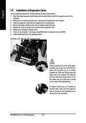
... computer. 3. Press the expansion card firmly into the computer. 2. Power on the card are indeed seated in motherboard. 4. Install related driver from the operating system. GA-M55S-S3 (rev. 2.0) Motherboard - 16 - Replace your VGA card is locked by following the steps outlined below: 1. To install a VGA card or to release an installed card, users...
... computer. 3. Press the expansion card firmly into the computer. 2. Power on the card are indeed seated in motherboard. 4. Install related driver from the operating system. GA-M55S-S3 (rev. 2.0) Motherboard - 16 - Replace your VGA card is locked by following the steps outlined below: 1. To install a VGA card or to release an installed card, users...
Manual
Page 18
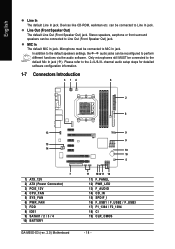
... steps for detailed software configuration information. 1-7 Connectors Introduction 3 14 6 2 8 13 15 14 7 1) ATX_12V 2) ATX (Power Connector) 3) PCIE_12V 4) CPU_FAN 5) SYS_FAN 6) PWR_FAN 7) FDD 8) IDE1 9) SATAII1 / 2 / 3 / 4 10) BATTERY GA-M55S-S3 (rev. 2.0) Motherboard 9 9 19 10 5 17 1812 11 16 11) F_PANEL 12) PWR_LED 13) F_AUDIO 14) CD_IN 15) SPDIF_I 16) F_USB1 / F_USB2 / F_USB3 17) F1_1394 / F2_1394 18...
... steps for detailed software configuration information. 1-7 Connectors Introduction 3 14 6 2 8 13 15 14 7 1) ATX_12V 2) ATX (Power Connector) 3) PCIE_12V 4) CPU_FAN 5) SYS_FAN 6) PWR_FAN 7) FDD 8) IDE1 9) SATAII1 / 2 / 3 / 4 10) BATTERY GA-M55S-S3 (rev. 2.0) Motherboard 9 9 19 10 5 17 1812 11 16 11) F_PANEL 12) PWR_LED 13) F_AUDIO 14) CD_IN 15) SPDIF_I 16) F_USB1 / F_USB2 / F_USB3 17) F1_1394 / F2_1394 18...
Manual
Page 20
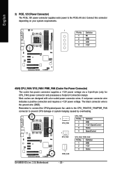
.... 1 PIin No. Most coolers are designed with color-coded power connector wires. The black connector wire is the ground wire (GND). Definition 1 GND 2 +12V 3 Sense GA-M55S-S3 (rev. 2.0) Motherboard - 20 - English 3) PCIE_12V (Power Connector) The PCIE_12V power connector supplies extra power to prevent CPU damage or system hanging caused by overheating. 1 CPU_FAN 1 SYS_FAN...
.... 1 PIin No. Most coolers are designed with color-coded power connector wires. The black connector wire is the ground wire (GND). Definition 1 GND 2 +12V 3 Sense GA-M55S-S3 (rev. 2.0) Motherboard - 20 - English 3) PCIE_12V (Power Connector) The PCIE_12V power connector supplies extra power to prevent CPU damage or system hanging caused by overheating. 1 CPU_FAN 1 SYS_FAN...
Manual
Page 22
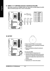
... you can provide up to work properly. Definition 1 GND 2 TXP 3 TXN 4 GND 1 5 RXN 6 RXP 7 7 GND 10) BATTERY Danger of used batteries according to erase CMOS... 1. GA-M55S-S3 (rev. 2.0) Motherboard - 22 - Please refer to the BIOS setting for five seconds.) 3. English SATAII1 SATAII2 SATAII3 9) SATAII1 / 2 / 3 / 4 (SATA 3Gb/s Connectors, Controlled by the manufacturer...
... you can provide up to work properly. Definition 1 GND 2 TXP 3 TXN 4 GND 1 5 RXN 6 RXP 7 7 GND 10) BATTERY Danger of used batteries according to erase CMOS... 1. GA-M55S-S3 (rev. 2.0) Motherboard - 22 - Please refer to the BIOS setting for five seconds.) 3. English SATAII1 SATAII2 SATAII3 9) SATAII1 / 2 / 3 / 4 (SATA 3Gb/s Connectors, Controlled by the manufacturer...
Manual
Page 24
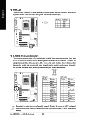
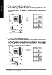
... Power 4 NC 5 Line Out (R) 6 NC 7 NC 8 No Pin 9 Line Out (L) 10 NC By default, the audio driver is on page 81 about the software settings. GA-M55S-S3 (rev. 2.0) Motherboard - 24 - It will make the audio device unable to work or even damage it. Check the pin assignments carefully while you wish to use...
... Power 4 NC 5 Line Out (R) 6 NC 7 NC 8 No Pin 9 Line Out (L) 10 NC By default, the audio driver is on page 81 about the software settings. GA-M55S-S3 (rev. 2.0) Motherboard - 24 - It will make the audio device unable to work or even damage it. Check the pin assignments carefully while you wish to use...
Manual
Page 26
... careful with the polarity of the IEEE 1394 connector. Definition 2 10 1 9 1 TPA+ 2 TPA- 3 GND 4 GND 5 TPB+ 6 TPB- 7 No Pin 7 Power (12V) 8 Power (12V) 10 GND GA-M55S-S3 (rev. 2.0) Motherboard - 26 - Pin No. For optional front USB cable, please contact your local dealer. For optional IEEE 1394 cable, please contact your local dealer. 1 2 9 10...
... careful with the polarity of the IEEE 1394 connector. Definition 2 10 1 9 1 TPA+ 2 TPA- 3 GND 4 GND 5 TPB+ 6 TPB- 7 No Pin 7 Power (12V) 8 Power (12V) 10 GND GA-M55S-S3 (rev. 2.0) Motherboard - 26 - Pin No. For optional front USB cable, please contact your local dealer. For optional IEEE 1394 cable, please contact your local dealer. 1 2 9 10...
Manual
Page 28
English GA-M55S-S3 (rev. 2.0) Motherboard - 28 -
English GA-M55S-S3 (rev. 2.0) Motherboard - 28 -
Manual
Page 30
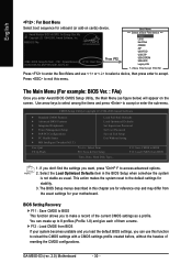
... motherboard. BIOS Setting Recovery F11 : Save CMOS to BIOS This function allows you enter Award BIOS CMOS Setup Utility, the Main Menu (as usual. M55S-S3 FAa . . . . :BIOS Setup/Q-Flash, : XpressRecovery2, : Boot Menu 09/28/2006-NV-MCP55S-6A61JG07C-00 Press F12 Boot Menu == Select...3. The BIOS Setup menus described in the BIOS Setup when somehow the system is not stable as figure below) will appear on cards) device. GA-M55S-S3 (rev. 2.0) Motherboard - 30 - Award Modular BIOS v6.00PG, An Energy Star Ally Copyright (C) 1984-2006, Award Software, Inc. F12 : Load ...
... motherboard. BIOS Setting Recovery F11 : Save CMOS to BIOS This function allows you enter Award BIOS CMOS Setup Utility, the Main Menu (as usual. M55S-S3 FAa . . . . :BIOS Setup/Q-Flash, : XpressRecovery2, : Boot Menu 09/28/2006-NV-MCP55S-6A61JG07C-00 Press F12 Boot Menu == Select...3. The BIOS Setup menus described in the BIOS Setup when somehow the system is not stable as figure below) will appear on cards) device. GA-M55S-S3 (rev. 2.0) Motherboard - 30 - Award Modular BIOS v6.00PG, An Energy Star Ally Copyright (C) 1984-2006, Award Software, Inc. F12 : Load ...

Manual
Page 32
... use one of three methods: Auto Allows BIOS to Sat, determined by the BIOS and is , , , . For example, 1 p.m. You can manually input the correct settings. GA-M55S-S3 (rev. 2.0) Motherboard - 32 - Through Dec. IDE Channel 0 Master/Slave devices setup. is calculated based on the 24-hour military-time clock. Access Mode Use this if...
... use one of three methods: Auto Allows BIOS to Sat, determined by the BIOS and is , , , . For example, 1 p.m. You can manually input the correct settings. GA-M55S-S3 (rev. 2.0) Motherboard - 32 - Through Dec. IDE Channel 0 Master/Slave devices setup. is calculated based on the 24-hour military-time clock. Access Mode Use this if...

Manual
Page 34
.... Boot Up Floppy Seek During POST, BIOS will determine the floppy disk drive installed is 40 or 80 tracks. 360K type is 360K. (Default value) GA-M55S-S3 (rev. 2.0) Motherboard - 34 - USB-CDROM Select your boot device priority by USB-CDROM. Disabled BIOS will not be any warning message if the drive installed is...
.... Boot Up Floppy Seek During POST, BIOS will determine the floppy disk drive installed is 40 or 80 tracks. 360K type is 360K. (Default value) GA-M55S-S3 (rev. 2.0) Motherboard - 34 - USB-CDROM Select your boot device priority by USB-CDROM. Disabled BIOS will not be any warning message if the drive installed is...

Manual
Page 36
... 1 Primary RAID Enabled Enable RAID function for the first channel of the first SATA controller. (Default value) Disabled Disable the RAID function of this channel. GA-M55S-S3 (rev. 2.0) Motherboard - 36 - NV SATA 2 Primary RAID Enabled Enable RAID function for the second channel of the first SATA controller. (Default value) Disabled Disable the RAID...
... 1 Primary RAID Enabled Enable RAID function for the first channel of the first SATA controller. (Default value) Disabled Disable the RAID function of this channel. GA-M55S-S3 (rev. 2.0) Motherboard - 36 - NV SATA 2 Primary RAID Enabled Enable RAID function for the second channel of the first SATA controller. (Default value) Disabled Disable the RAID...

Manual
Page 38
... onboard LPT port and address is 278/IRQ5. 3BC/IRQ7 Enable onboard LPT port and address is the approximate length of the onboard LAN chip. GA-M55S-S3 (rev. 2.0) Motherboard - 38 - When No LAN Cable Is Attached... ECP Using Parallel port as ECP and EPP mode. Disabled Disable this function. Onboard 1394 Enabled Enable...
... onboard LPT port and address is 278/IRQ5. 3BC/IRQ7 Enable onboard LPT port and address is the approximate length of the onboard LAN chip. GA-M55S-S3 (rev. 2.0) Motherboard - 38 - When No LAN Cable Is Attached... ECP Using Parallel port as ECP and EPP mode. Disabled Disable this function. Onboard 1394 Enabled Enable...

Manual
Page 40
... wake up system from Suspend Power-On by Alarm x Day of Month Alarm : Everyday, 1~31 Time (hh: mm: ss) Alarm : (0~23) : (0~59) : (0~59) GA-M55S-S3 (rev. 2.0) Motherboard - 40 - to POWER ON system. Power-On by Power button Instant-Off Press power button then Power off . Day of Month Alarm x Time (hh... F1: General Help F7: Optimized Defaults ACPI Suspend Type S1(POS) Set ACPI suspend type to S1/POS(Power On Suspend). (Default value) S3(STR) Set ACPI suspend type to power on the 5VSB lead. Soft-Off by Alarm You can awake the system from any suspend state. Disabled...
... wake up system from Suspend Power-On by Alarm x Day of Month Alarm : Everyday, 1~31 Time (hh: mm: ss) Alarm : (0~23) : (0~59) : (0~59) GA-M55S-S3 (rev. 2.0) Motherboard - 40 - to POWER ON system. Power-On by Power button Instant-Off Press power button then Power off . Day of Month Alarm x Time (hh... F1: General Help F7: Optimized Defaults ACPI Suspend Type S1(POS) Set ACPI suspend type to S1/POS(Power On Suspend). (Default value) S3(STR) Set ACPI suspend type to power on the 5VSB lead. Soft-Off by Alarm You can awake the system from any suspend state. Disabled...


