
User Manual
Page 4
Table of Contents GA-K8VT890-9 Motherboard Layout 6 Block Diagram ...7 Chapter 1 Hardware Installation 9 1-1 Considerations Prior to Installation 9 1-2 Feature Summary 10 1-3 Installation of the CPU and Fan Heat Sink 12 ... of Memory 14 1-5 Installation of Expansion Cards 16 1-6 I/O Back Panel Introduction 17 1-7 Connectors Introduction 18 Chapter 2 BIOS Setup 29 The Main Menu (For example: BIOS Ver. : D2 30 2-1 Standard CMOS Features 32 2-2 Advanced BIOS Features 34 2-3 Integrated Peripherals 35 2-4 Power Management Setup 37 2-5 PnP/PCI Configurations 39 2-6 PC Health Status 40 ...
Table of Contents GA-K8VT890-9 Motherboard Layout 6 Block Diagram ...7 Chapter 1 Hardware Installation 9 1-1 Considerations Prior to Installation 9 1-2 Feature Summary 10 1-3 Installation of the CPU and Fan Heat Sink 12 ... of Memory 14 1-5 Installation of Expansion Cards 16 1-6 I/O Back Panel Introduction 17 1-7 Connectors Introduction 18 Chapter 2 BIOS Setup 29 The Main Menu (For example: BIOS Ver. : D2 30 2-1 Standard CMOS Features 32 2-2 Advanced BIOS Features 34 2-3 Integrated Peripherals 35 2-4 Power Management Setup 37 2-5 PnP/PCI Configurations 39 2-6 PC Health Status 40 ...

User Manual
Page 5
Channel Audio Function Introduction 69 4-2 Troubleshooting 77 - 5 - Chapter 3 Drivers Installation 45 3-1 Install Chipset Drivers 45 3-2 Software Application 46 3-3 Software Information 46 3-4 Hardware Information 47 3-5 Contact Us ...47 Chapter 4 Appendix 49 4-1 Unique Software Utilities 49 4-1-1 EasyTune 5 Introduction 49 4-1-2 Xpress Recovery Introduction 50 4-1-3 Flash BIOS Method Introduction 53 4-1-4 Serial ATA BIOS Setting Utility Introduction 62 4-1-5 2- / 4- / 6- / 8-
Channel Audio Function Introduction 69 4-2 Troubleshooting 77 - 5 - Chapter 3 Drivers Installation 45 3-1 Install Chipset Drivers 45 3-2 Software Application 46 3-3 Software Information 46 3-4 Hardware Information 47 3-5 Contact Us ...47 Chapter 4 Appendix 49 4-1 Unique Software Utilities 49 4-1-1 EasyTune 5 Introduction 49 4-1-2 Xpress Recovery Introduction 50 4-1-3 Flash BIOS Method Introduction 53 4-1-4 Serial ATA BIOS Setting Utility Introduction 62 4-1-5 2- / 4- / 6- / 8-

User Manual
Page 11
... transfer rate of 2 SATA connections - Hardware Installation supported on the Win 2000/XP operating systems Use of licensed AWARD BIOS Supports Q-Flash Supports @BIOS Supports EasyTune 5 (Note 4) Over Clock via BIOS (CPU) Over Voltage via BIOS (CPU/ DIMM) ATX form factor; 29.4cm x 22.5cm (Note 4) EasyTune 5 functions may vary depending on different motherboards...
... transfer rate of 2 SATA connections - Hardware Installation supported on the Win 2000/XP operating systems Use of licensed AWARD BIOS Supports Q-Flash Supports @BIOS Supports EasyTune 5 (Note 4) Over Clock via BIOS (CPU) Over Voltage via BIOS (CPU/ DIMM) ATX form factor; 29.4cm x 22.5cm (Note 4) EasyTune 5 functions may vary depending on different motherboards...

User Manual
Page 14
... modules, please comply with each slot. Memory modules have a foolproof insertion design. Insert the DIMM memory module vertically into the DIMM socket. GA-K8VT890-9 Motherboard - 14 - Memory modules are unable to prevent hardware damage. 3. The memory capacity used . 2. Fig.2 Close the plastic clip... the DIMM sockets to remove the DIMM module. It is supported by the motherboard. The motherboard supports DDR memory modules, whereby BIOS will automatically detect memory capacity and specifications. Notch DDR Fig.1 The DIMM socket has a notch, so the DIMM memory module...
... modules, please comply with each slot. Memory modules have a foolproof insertion design. Insert the DIMM memory module vertically into the DIMM socket. GA-K8VT890-9 Motherboard - 14 - Memory modules are unable to prevent hardware damage. 3. The memory capacity used . 2. Fig.2 Close the plastic clip... the DIMM sockets to remove the DIMM module. It is supported by the motherboard. The motherboard supports DDR memory modules, whereby BIOS will automatically detect memory capacity and specifications. Notch DDR Fig.1 The DIMM socket has a notch, so the DIMM memory module...
User Manual
Page 16
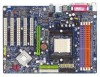
... your VGA card is locked by following the steps outlined below: 1. Power on the computer, if necessary, setup BIOS utility of the expansion card. 6. Install related driver from the computer. 3. English 1-5 Installation of Expansion Cards You can install your expansion card by the ...Express x 16 slot when you try to the onboard PCI Express x 16 slot and press firmly down on the card are indeed seated in motherboard. 4. GA-K8VT890-9 Motherboard - 16 - Be sure the metal contacts on the slot. Please align the VGA card to install/uninstall the VGA card. Make sure your ...
... your VGA card is locked by following the steps outlined below: 1. Power on the computer, if necessary, setup BIOS utility of the expansion card. 6. Install related driver from the computer. 3. English 1-5 Installation of Expansion Cards You can install your expansion card by the ...Express x 16 slot when you try to the onboard PCI Express x 16 slot and press firmly down on the card are indeed seated in motherboard. 4. GA-K8VT890-9 Motherboard - 16 - Be sure the metal contacts on the slot. Please align the VGA card to install/uninstall the VGA card. Make sure your ...

User Manual
Page 21
...). 40 39 2 IDE1 1 IDE2 7) SATA0 / SATA1 (Serial ATA Connectors) Serial ATA can then connect to the computer via an IDE connector. Please refer to the BIOS setting for information on settings, please refer to the instructions located on one IDE cable, and the single IDE cable can provide up to work...
...). 40 39 2 IDE1 1 IDE2 7) SATA0 / SATA1 (Serial ATA Connectors) Serial ATA can then connect to the computer via an IDE connector. Please refer to the BIOS setting for information on settings, please refer to the instructions located on one IDE cable, and the single IDE cable can provide up to work...

User Manual
Page 27
Definition 1 1 Signal 2 GND - 27 - Hardware Installation Pin No. English 17) CI (Chassis Intrusion, Case Open) This 2-pin connector allows your system to enable or disable the "case open" item in BIOS if the system case has been remove.
Definition 1 1 Signal 2 GND - 27 - Hardware Installation Pin No. English 17) CI (Chassis Intrusion, Case Open) This 2-pin connector allows your system to enable or disable the "case open" item in BIOS if the system case has been remove.

User Manual
Page 29
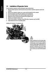
... Q-Flash allows the user to quickly and easily update or backup BIOS without entering the operating system. @BIOS is a Windows-based utility that describes the appropriate keys to a new BIOS, either GIGABYTE's Q-Flash or @BIOS utility can enter the BIOS setup screen by pressing "Ctrl + F1". To exit the Help... Window press . - 29 - Status Page Setup Menu / Option Page Setup Menu Press F1 to pop up BIOS for Option Page Setup ...
... Q-Flash allows the user to quickly and easily update or backup BIOS without entering the operating system. @BIOS is a Windows-based utility that describes the appropriate keys to a new BIOS, either GIGABYTE's Q-Flash or @BIOS utility can enter the BIOS setup screen by pressing "Ctrl + F1". To exit the Help... Window press . - 29 - Status Page Setup Menu / Option Page Setup Menu Press F1 to pop up BIOS for Option Page Setup ...
User Manual
Page 30
... If you wish to accept or enter the sub-menu. CMOS Setup Utility-Copyright (C) 1984-2004 Award Software ` Standard CMOS Features ` Advanced BIOS Features ` Integrated Peripherals ` Power Management Setup ` PnP/PCI Configurations ` PC Health Status ` Frequency/Voltage Control ESC: Quit F8: Q-Flash Top... Exit Setup Time, Date, Hard Disk Type... If you can't find the setting you enter Award BIOS CMOS Setup Utility, the Main Menu (as "Enabled". Use arrow keys to select among the items and press to maximize the performance of your motherboard. GA-K8VT890-9 Motherboard - 30 -
... If you wish to accept or enter the sub-menu. CMOS Setup Utility-Copyright (C) 1984-2004 Award Software ` Standard CMOS Features ` Advanced BIOS Features ` Integrated Peripherals ` Power Management Setup ` PnP/PCI Configurations ` PC Health Status ` Frequency/Voltage Control ESC: Quit F8: Q-Flash Top... Exit Setup Time, Date, Hard Disk Type... If you can't find the setting you enter Award BIOS CMOS Setup Utility, the Main Menu (as "Enabled". Use arrow keys to select among the items and press to maximize the performance of your motherboard. GA-K8VT890-9 Motherboard - 30 -

User Manual
Page 31
... to the system and Setup, or just to CMOS and exit setup. „ Exit Without Saving Abandon all CMOS value changes and exit setup. - 31 - BIOS Setup It allows you to limit access to the system. „ Save & Exit Setup Save CMOS value settings to Setup. „ Set User Password Change...
... to the system and Setup, or just to CMOS and exit setup. „ Exit Without Saving Abandon all CMOS value changes and exit setup. - 31 - BIOS Setup It allows you to limit access to the system. „ Save & Exit Setup Save CMOS value settings to Setup. „ Set User Password Change...

User Manual
Page 32
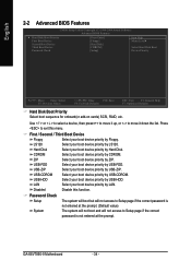
... of three methods: • Auto Allows BIOS to automatically detect IDE devices during POST. (Default value) • None Select this option for faster system start up . • Manual User can use one of currectly installed hard drive. GA-K8VT890-9 Motherboard - 32 - Day The day,... : Large/Auto(default:Auto) Capacity Capacity of two methods: • Auto Allows BIOS to automatically detect SATA IDE devices during POST(default) • None Select this to Sat, determined by the BIOS and is , , , . English 2-1 Standard CMOS Features Date (mm:dd:yy...
... of three methods: • Auto Allows BIOS to automatically detect IDE devices during POST. (Default value) • None Select this option for faster system start up . • Manual User can use one of currectly installed hard drive. GA-K8VT890-9 Motherboard - 32 - Day The day,... : Large/Auto(default:Auto) Capacity Capacity of two methods: • Auto Allows BIOS to automatically detect SATA IDE devices during POST(default) • None Select this to Sat, determined by the BIOS and is , , , . English 2-1 Standard CMOS Features Date (mm:dd:yy...

User Manual
Page 33
...Number of heads Precomp Write precomp Landing Zone Landing zone Sector Number of sectors Drive A / Drive B The category identifies the types of the BIOS will stop for all other All, But Diskette errors. (Default value) The system boot will stop if an error is present during power up...drive; 1.2M byte capacity (3.5 inch when 3 Mode is typically 512K for systems with 512K memory installed on the motherboard. All Errors Whenever the BIOS detects a non-fatal error the system will be prompted. All, But Disk/Key The system boot will not stop for Japan Area) Disabled ...
...Number of heads Precomp Write precomp Landing Zone Landing zone Sector Number of sectors Drive A / Drive B The category identifies the types of the BIOS will stop for all other All, But Diskette errors. (Default value) The system boot will stop if an error is present during power up...drive; 1.2M byte capacity (3.5 inch when 3 Mode is typically 512K for systems with 512K memory installed on the motherboard. All Errors Whenever the BIOS detects a non-fatal error the system will be prompted. All, But Disk/Key The system boot will not stop for Japan Area) Disabled ...
User Manual
Page 34
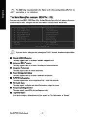
... and will not access to move it down the list. LAN Select your boot device priority by LAN. English 2-2 Advanced BIOS Features CMOS Setup Utility-Copyright (C) 1984-2004 Award Software Advanced BIOS Features ` Hard Disk Boot Priority First Boot Device Second Boot Device Third Boot Device Password Check [Press Enter] [Floppy] [Hard... Select boot sequence for onboard(or add-on cards) SCSI, RAID, etc. First / Second / Third Boot Device Floppy Select your boot device priority by Floppy. GA-K8VT890-9 Motherboard - 34 -
... and will not access to move it down the list. LAN Select your boot device priority by LAN. English 2-2 Advanced BIOS Features CMOS Setup Utility-Copyright (C) 1984-2004 Award Software Advanced BIOS Features ` Hard Disk Boot Priority First Boot Device Second Boot Device Third Boot Device Password Check [Press Enter] [Floppy] [Hard... Select boot sequence for onboard(or add-on cards) SCSI, RAID, etc. First / Second / Third Boot Device Floppy Select your boot device priority by Floppy. GA-K8VT890-9 Motherboard - 34 -
User Manual
Page 35
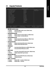
... onboard Serial ATA function. (Default value) Disabled Disable onboard Serial ATA function. USB 1.1 Controller Enabled Enable USB 1.1 controller. (Default value) Disabled Disable USB 1.1 controller. - 35 - BIOS Setup AC97 Audio Auto Disabled Auto detect onboard AC97 audio function. (Default value) Disable onboard AC97 audio function. OnChip IDE Channel0 Enabled Disabled Enable onboard...
... onboard Serial ATA function. (Default value) Disabled Disable onboard Serial ATA function. USB 1.1 Controller Enabled Enable USB 1.1 controller. (Default value) Disabled Disable USB 1.1 controller. - 35 - BIOS Setup AC97 Audio Auto Disabled Auto detect onboard AC97 audio function. (Default value) Disable onboard AC97 audio function. OnChip IDE Channel0 Enabled Disabled Enable onboard...

User Manual
Page 36
... Port IRQ to 300. English USB 2.0 Controller Enabled Enable USB 2.0 controller. (Default value) Disabled Disable USB 2.0 controller. Onboard Serial Port 2 Auto BIOS will automatically setup the port 1 address. Enable onboard Serial port 1 and address is 2F8/IRQ3. (Default value) 3E8/IRQ4 Enable onboard Serial port ...LPT port and address is 378/IRQ7. (Default value) 278/IRQ5 3BC/IRQ7 Enable onboard LPT port and address is 278/IRQ5. GA-K8VT890-9 Motherboard - 36 - ECP Using Parallel port as ECP and EPP mode. Disabled Disable onboard Serial port 2. Parallel Port Mode SPP...
... Port IRQ to 300. English USB 2.0 Controller Enabled Enable USB 2.0 controller. (Default value) Disabled Disable USB 2.0 controller. Onboard Serial Port 2 Auto BIOS will automatically setup the port 1 address. Enable onboard Serial port 1 and address is 2F8/IRQ3. (Default value) 3E8/IRQ4 Enable onboard Serial port ...LPT port and address is 378/IRQ7. (Default value) 278/IRQ5 3BC/IRQ7 Enable onboard LPT port and address is 278/IRQ5. GA-K8VT890-9 Motherboard - 36 - ECP Using Parallel port as ECP and EPP mode. Disabled Disable onboard Serial port 2. Parallel Port Mode SPP...

User Manual
Page 37
...) Full-On When AC-power back to power on the system. Mouse Power On Disabled Enabled Disable this function. (Default value) Password Enter from S3. BIOS Setup English 2-4 Power Management Setup CMOS Setup Utility-Copyright (C) 1984-2004 Award Software Power Management Setup ACPI Suspend Type x USB Dev Wake-Up From S3...
...) Full-On When AC-power back to power on the system. Mouse Power On Disabled Enabled Disable this function. (Default value) Password Enter from S3. BIOS Setup English 2-4 Power Management Setup CMOS Setup Utility-Copyright (C) 1984-2004 Award Software Power Management Setup ACPI Suspend Type x USB Dev Wake-Up From S3...

User Manual
Page 39
BIOS Setup Auto assign IRQ to PCI 3. (Default value) Set IRQ 3,4,5,7,9,10,11,12,14,15 to PCI 2. Auto assign IRQ to PCI 2. (Default value) Set ...
BIOS Setup Auto assign IRQ to PCI 3. (Default value) Set IRQ 3,4,5,7,9,10,11,12,14,15 to PCI 2. Auto assign IRQ to PCI 2. (Default value) Set ...
User Manual
Page 40
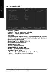
... reset "Case Opened" value, set "Reset Case Open Status" to Enabled then save BIOS setup and restart your system. Case Opened If the case is closed, "Case Opened" will show "No". Current CPU Temperature Detect CPU temperature automatically. GA-K8VT890-9 Motherboard - 40 - Current CPU/SYSTEM FAN Speed (RPM) Detect CPU/SYSTEM fan speed...
... reset "Case Opened" value, set "Reset Case Open Status" to Enabled then save BIOS setup and restart your system. Case Opened If the case is closed, "Case Opened" will show "No". Current CPU Temperature Detect CPU temperature automatically. GA-K8VT890-9 Motherboard - 40 - Current CPU/SYSTEM FAN Speed (RPM) Detect CPU/SYSTEM fan speed...
User Manual
Page 41
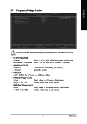
... automatically. (Default value) Disable this function. CPU OverVoltage Control Auto +5%, +7.5%, +10% Supply voltage as CPU required. (Default value) Increase voltage range as user selected. - 41 - BIOS Setup DIMM OverVoltage Control Auto Supply voltage as DDR module required. (Default value) +0.1V, +0.2V, +0.3V Increase voltage range as user selected. English 2-7 Frequency/Voltage...
... automatically. (Default value) Disable this function. CPU OverVoltage Control Auto +5%, +7.5%, +10% Supply voltage as CPU required. (Default value) Increase voltage range as user selected. - 41 - BIOS Setup DIMM OverVoltage Control Auto Supply voltage as DDR module required. (Default value) +0.1V, +0.2V, +0.3V Increase voltage range as user selected. English 2-7 Frequency/Voltage...

User Manual
Page 42
... performance. For example, the same hardware configuration might not run properly with Windows XP, but works smoothly with Windows NT. GA-K8VT890-9 Motherboard - 42 - Different system configuration (both hardware component and OS) will increase hardware working speed. English 2-8 Top... Performance CMOS Setup Utility-Copyright (C) 1984-2004 Award Software ` Standard CMOS Features Top Performance ` Advanced BIOS Features Load Fail-Safe Defaults ` Integrated Peripherals Top Performance Load Optimized Defaults ` Power Management Setup Set Supervisor Password ` PnP...
... performance. For example, the same hardware configuration might not run properly with Windows XP, but works smoothly with Windows NT. GA-K8VT890-9 Motherboard - 42 - Different system configuration (both hardware component and OS) will increase hardware working speed. English 2-8 Top... Performance CMOS Setup Utility-Copyright (C) 1984-2004 Award Software ` Standard CMOS Features Top Performance ` Advanced BIOS Features Load Fail-Safe Defaults ` Integrated Peripherals Top Performance Load Optimized Defaults ` Power Management Setup Set Supervisor Password ` PnP...


